Service Host
Version 1.0 | Published November 15, 2017 ©
Channel Recorder Configuration
You can configure Channel Recorder at any time after successfully registering an instance. For any configuration changes to take effect, you must restart the instance.
Every plugin of Service Host has its own configuration page. For more information, refer to the Service Host documentation.
Every plugin configuration page consist of two main sections:
The Plugin Configuration Section is unique for each plugin.
From the Service Host Section, you can set specific command arguments to the plugin. This is useful mainly for debugging purposes.
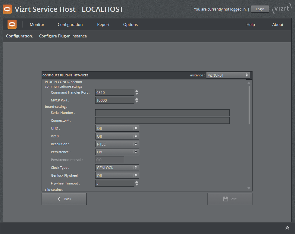
Plugin Configuration Section
The Plugin Configuration Section consists of 3 parts:
-
Communication Settings (changes to these settings only take effect by restarting the Channel Recorder instance).
-
Command Handler Port: This is the port used to communicate with Channel Recorder via Viz Send. The default value is 6810.
-
MVCP Port: This is the port used to communicate with Channel Recorder using MVCP. Some Vizrt products, such as Viz Dart, use this protocol to communicate with Channel Recorder. The default value is 10000.

-
-
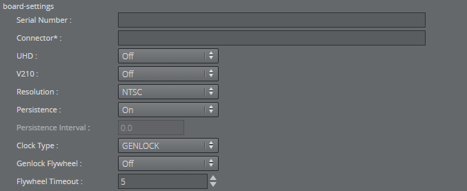
Board Settings (changes to these settings only take effect by restarting the Channel Recorder instance).
-
Serial Number: Select the board with the specified serial number. If no serial number is specified, the first detected board is selected. By default, no value is specified.
Tip: The serial number on Matrox video boards can be found in the hardware tab of Matrox X.info and it usually starts with an A.
-
Connector: This will select the connector that will be used for recording live input. This is a required value. The default value is empty.
-
UHD: Enable detection of UHDTV signals. When set to On, the Channel Recorder scans the signal resolution on the four corresponding input connectors. If four 3G signals are detected, they are interpreted as one UHDTV signal. When set to Off, the four connectors are treated as separate 3G signals. The default value is Off.
-
V210: Use the 10-bit surface format V210. This is needed to record XAVC. It also increases performance when for example recording ProRes. This surface format is not supported on the Matrox X.mio2+. The default value is Off.
-
Resolution: Set the default resolution. The possible values are: NTSC, PAL, 720p50, 720p60M, 1080i25, 1080p60, 1080i30M, 1080i30, 1080p50, 1080p60M and 1080p60. The default value is NTSC.
-
Persistence: Choose if a backup of the scheduled recording is needed. This is only useful for scheduled recordings. The default value is Off.
-
Persistence Interval: Define, in seconds, the interval in which the backup is written to disk. The default value is 0.
-
Clock Type: Define what type of clock is used for recording. The possible values are: GENLOCK and INPUT. The default value is GENLOCK.
Tip: INPUT clock type is recommended when the GENLOCK signal is unstable. INPUT clock also allows recording when no input signal is detected.
-
Genlock Flywheel: If Clock Type is GENLOCK, also use the flywheel in case the genlock signal is lost.
-
Flywheel Timeout: Set the timeout of the genlock flywheel in seconds. This defines the time until the genlock switches to free run, as well as the maximum time the flywheel can use to resynchronize. The default value is 5.0.
-
-
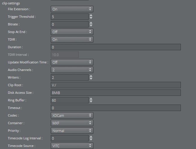
Clip Settings (some of these settings can be changed when Channel Recorder is running. Refer to Channel Recorder Control Commands).
-
File Extensions: Enable or disable automatically adding a file extension to the file name. If this feature is turned off, the client application has full control over the file name. The default value is Off.
-
Trigger Threshold: If a timed command misses the execution time, but is still within the trigger threshold, it will be executed (late). Outside of this window, the command is ignored until the next time the timecode is received. The value can either be a number of frames or a timecode-based relative value. The default value is 5.
-
Bitrate: Set the bitrate for the video encoding. The value can either be applied as bps (bits per second) or as mbps (megabits per second). Not all codecs allow changes to the bitrate. In such cases, this value is ignored. The default value is 0.
-
Stop At End: Set the default value at the end of recording. The default value is Off.
-
TDIR: Enable or disable Time Delayed Instant Replay. The default is On.
-
Duration: Set the default duration of the recording. The default value is 0.
-
TDIR Interval: Set the interval of file header updates in TDIR recordings. The value is in seconds and fractions of seconds, meaning both 11.1 and 11.2 are considered valid values. Minimum allowed value is 10.0, which is interpreted by Channel Recorder as every frame. The maximum value is 60.0. The default value is 10.0.
-
Update Modification Time: Update the modification time of the recorded clip regardless of TDIR setting value. The default value is On.
-
Audio Channels: Set the number of audio channels to record. How many channels are actually recorded depends on the codec and the input signal. The default value is 2.
-
Writers: Set the number of writers to initialize. The default value is 2.
Tip: More writers increase memory consumption however it will prevent failed recording when the scheduled recordings are very close to each other in the order of 5 to 10 seconds.
-
Clip Root: Set the default folder for the recordings. The default value is V:/.
-
Disk Access Size: Set the size of data blocks written to the disk in byte. Postfixes like KiB, Kb, k, etc., are allowed, but must not be separated from the value with a blank space. The default value is 8MiB (2*4194304 bytes). The minimum value is 32KiB (32768 bytes).
Tip: KiB and k multiplies the value by 1024. kb multiplies the value by 1000. The same works with m for mega and g for giga.
-
Ring Buffer: Set the size of the capture ring buffer. The default value is 60.
-
Timeout: Set the timeout for the capture operation in milliseconds. If the recorder reports timeout errors, increasing the timeout could help. The value can be in frames or in timecode format: 00:00:00:00. The default value is 0.
-
Codec: Set the codec type of the recorded file. The possible values are: DvCam, DvCPro, Dv50, IFrame, XDCam, AVCIntra50, AVCIntra100, ProRes. The default value is XDCam.
-
Container: AVCINTRAMXF, AVI, DVCPROMXF, MOV, MXF, XAVCMXF, XDCAMMXF.
-
Priority: Set the process priority class. The values correspond to the Windows process priority. The default value is Normal.
-
Timecode Log Interval: Specify the interval at which the current timecode is logged. The value can either be a number of frames or a timecode-based relative value. The default value is 0, which means that every full second is logged.
-
Timecode Source: Specify the timecode source. The default value is VITC.
-
-
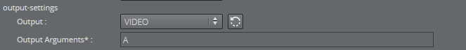
Output Settings (these settings can be changed when Channel Recorder is running. Refer to Channel Recorder Control Commands).
-
Output: Specify the output mode. The possible values are: VIDEO, CODER, NONE. The default value is NONE.
-
Output Arguments: Arguments for the selected output mode. For CODER it is [shared memory name], [proxy hostname], [proxy port] and for VIDEO it is [connector name].
Tip: Only one type of output can be configured at startup using the web interface. However, after startup, it is still possible to configure another output via Viz Send.
-
Service Host Section
One setting can be set in this section:
-
Arguments: Specify the arguments that are going to be passed to Channel Recorder.
An example of a string that can be used for enabling log level debug is: -v -l debug
See Also