
Tracking Hub Administrator Guide
Version 1.4 | Published October 30, 2020 ©
Lens File Editor
The new Lensfile Editor is a web based application hosted by Tracking Hub. It runs independently of Studio Manager or a Viz Engine. To use the Lens file editor, use one of the supported browsers and navigate to http://trackinghub_hostname:9090.
Note: The port needs to be configured first in Studio Manager, see Port Configuration.
The web browser needs to support WebSockets, Canvas Rendering and WebGL technologies. Please also make sure the configured port is not blocked by any firewall.
The Lensfile Editor is currently supported on the following browsers:
-
Chrome
-
Firefox
-
Safari
Port Configuration
The port used by the Lens File Editor needs to be configured in the Studio Manager.
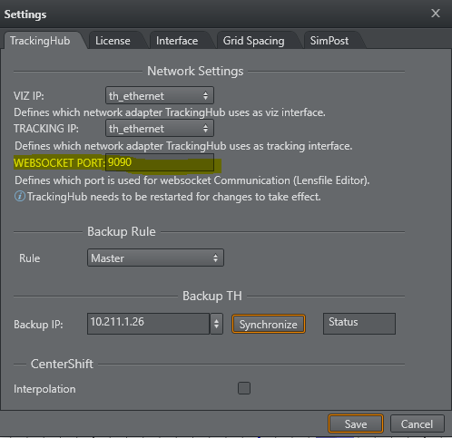
Info: Any change of this value is applied immediately without pressing the Save button.
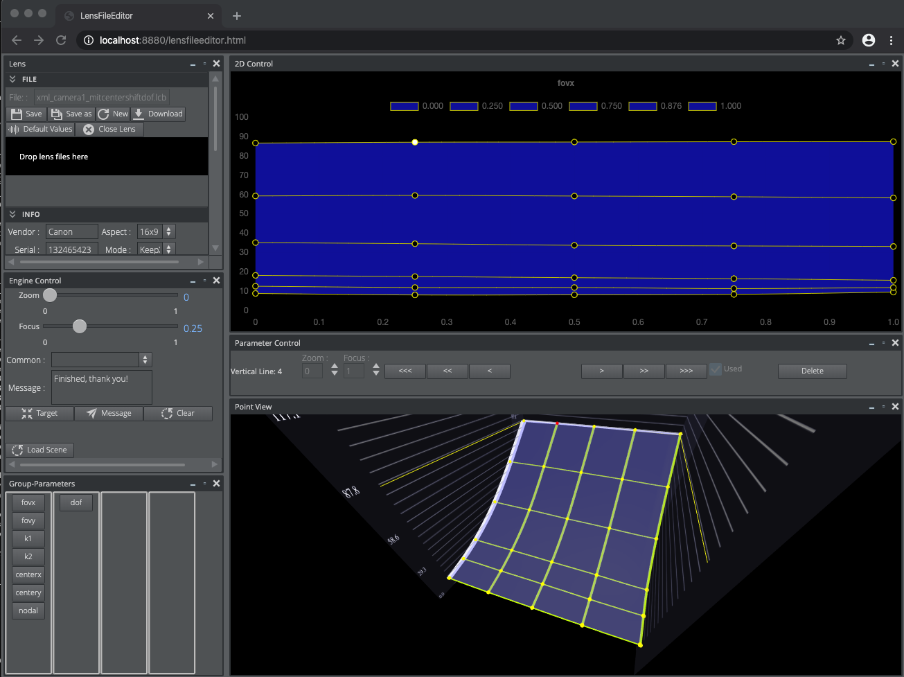
The Main Window and Contained Areas
The main window consists of six regions or portals and several modal windows.
Camera Selection
After the connection to the Tracking Hub is established, the Lensfile Editor shows all lens files, ready to be calibrated. The Rig, Service and Engine IP columns identify uniquely the Rig/Camera combination to be calibrated. The lensfile column shows the name of the lensfile which is loaded in the rig structure. The ID is mainly the ID of the camera service.
A lens file can be attached to more than one service. As soon as the user selects a Rig/Camera combination, a copy of the lensfile is loaded into the selected service. All other camera services are not affected.
As soon as a combination is selected, it is locked in Tracking Hub and can not be calibrated from another browser instance. The lock is released as soon as the browser window closes. So it is possible to calibrate different lenses at the same time, but not the same rig/camera combination.
To start a calibration, select one of the table rows and press Calibrate. The window disappears and the lens data is loaded into the window.
Lens Portlet
The Lens Portlet is structured into three sections.
File Section
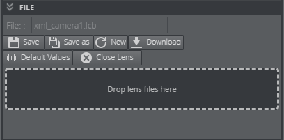
The Save button forces Tracking Hub to store the lens data into the lensfiles/lensfile folder of the configuration directory. When selecting a combination of Rig/Camera, the name of the lens file is added into the File text field. When pressing Save, the loaded lensfile is overwritten. Save As opens a window where the user can enter a new lens file name.
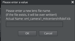
After pressing OK, the actual lens is saved on the Tracking Hub and automatically loaded. You need to save the configuration in Studio Manager to make the changed lens file permanent in the configuration!
-
New: Closes the current lens file and allows the user to start with a complete new calibration task. To generate the approximate field of view values you need to enter the focal length and multiplication values in the info section and then press Default Values to calculate an approximation.
-
Download: Exports or shares your lens file. This sends the XML file from the Tracking Hub to your local computer.
-
Default Values: Starts from the beginning by resetting all values back to the default ones. The filename stays the same.
-
Close Lens: Releases the file lock from this lens and close the calibration process. The user is presented with a dialog to select a new rig.
If you want to use an existing lens file, you can upload it to Tracking Hub by using the Drop zone. Simply drop a XML lens file to use it inside Tracking Hub. After dropping a XML file to the drop zone, a dialog pops up showing the file content as RAW XML file. A user can format it by using the Format button once.
Note: You need to press the Reload button in Studio Manager to select a new created lensfile.
Info Section
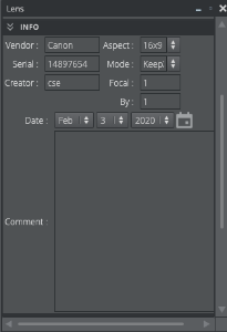
All fields should be filled with care, especially the Focal Length and Focal Multiplier fields. In case of a new lens, the Lensfile editor calculates base FoV values out of this information. The dialog only accepts float numbers in the Focal Length and Focal Multiplier fields. The Aspect mode defines if the lens is used as 16x9 of 4x3.
For clarification: Tracking Hub calculates the field of view X value from field of view Y. During calibration, this value defines how the Tracking Hub adjusts these values during dragging a point.
Later on and during operation, this value is defined in the Lensfile rig of Tracking Hub.
Setting Section
In the settings section the user can adjust the point size of the 3D an 2D view.
Calibration Scene
The calibration scene location can also be set here. Best practice is to enter the UUID of the scene there.
This is the scene going to be load if someone uses the "Load Scene" button in the Engine Control Section.
By pressing Save Settings, these settings are saved as cookie in your browser.
Group Portlet
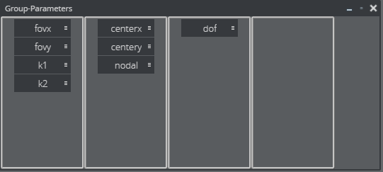
The new Lensfile Editor introduces the new concept of parameter groups. The old Lensfile Editor had only the principle of measure points.
While field of view and k1 and k2 change for every zoom and focus step, center shift and nodal point distance don't show this behavior. For these parameters only a few calibration points are needed, whereas for fov 50 or more measure points are necessary. Measure points are no longer defined directly. Measure points are defined by the crossing of horizontal and vertical measure lines. These lines can be moved, deleted and inserted at any time during calibration. Even when points are already measured, the line can be moved to a better location.
By moving a parameter from a 7x7 group into a 2x2 group, only four parameters are mapped into the new group.
Tip: Always create the groups before you start calibration.
Engine Control
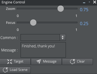
The Engine portlet works in combination with the calibration scene.
It is also possible to select one of the common messages in the Common drop box or enter any other message in the Message text field. By clicking the Send Message button, the message is displayed on the Engine screen. The message can be cleared by clicking the Clear button.
The Load Scene button forces Viz Engine to load the scene, the user entered in the Calibration Scene field of the settings section.
Calibration Scene
Viz Tracking Hub comes with a default calibration scene (as viz Archive).
This scene has been designed to be used with the Lens File editor and allows interaction with the person operating the camera.
Info: The archive of this scene is located on the FTP Tracking Hub download folder.
Info: The scene is loaded into the Front Layer of Viz Engine by default.
The scene must be imported into the database and then loaded into the Front Layer of the Engine.
In combination with the Engine Control portlet, the person running calibrating the lens can communicated with the camera operator.
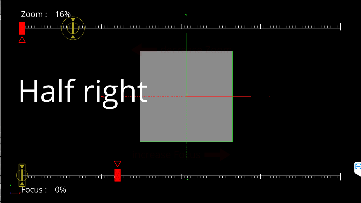
This special scene shows the target points that need to be calibrated by changing zoom and focus values and visually assist the operator. New target points can be send to the Engine using the Send button. Whenever a new point is selected, whether in the 2D or 3D portlet, the new zoom and focus values are set in the Zoom and Focus fields of the Engine portlet.
Parameter Control and Views
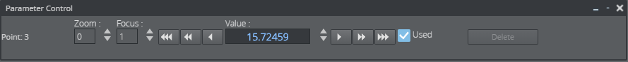
The Parameter portlet and the 2D and 3D views work close together. Whenever a point or line is selected in the views, the parameter control changes to the selected value and reflects all possible input on the selected objects.
The 3D View Control adjusts the minimal, maximal and scale value of the displayed data in the 3D View. Usually, these values don't need to be changed, because the 3D view is linked to the 2D view. In rare cases, if the user wants to inspect a special point or region of the lens, these values can be used.
-
Min: The minimum, bottom of the displayed data.
-
Max: The maximum, top of the displayed data.
The 2D View Controls the user can select the diagram type of the 2D display. Type can define two values: Zoom and Focus:
-
Focus: The X axis defines the focus range (0 to 1), while the Y axis shows the value of the calibrated points.
-
Zoom: The X axis defines the zoom range (0 to 1), while the Y axis shows the value of the calibrated points.
During calibration the focus diagram is the preferred one.
In case of a selected point, the value of the point can be modified. The modify divisor defines the amount of change, when the user clicks on the up and down button of the value. The base of this value is defined as the zoom area in the 2D and 3D view. 10 means, that the value is increased or decreased the zoom are divided by 10, 100 or 1000. This is valid for line movement as well.
A selected line can be moved between its left and right, or upper and lower neighbor. The Modify Divisor again defines the step size of the movement.
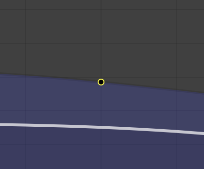
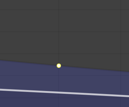
As soon as a point has been modified, the point is displayed in yellow and its value is used in the spline interpolation. This yellow state can canceled by unchecking the Used checkbox. Unchecking Used activates the blue state of the point and its value is defined from the calibrated points around.
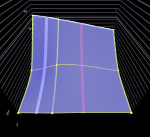
3D View
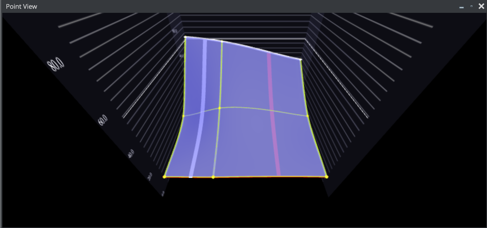
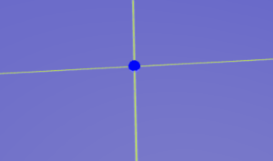
The 3D View shows the lens in a 3D Diagram. Focus is drawn in the X-Axis, Zoom in the Z-Axis. The lens is drawn as a blue surface, and the measure points as Spheres. Depending on the status of the measure points, different colors are used.
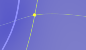
Point and Line Selection
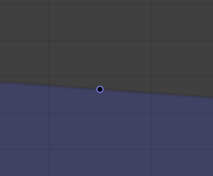
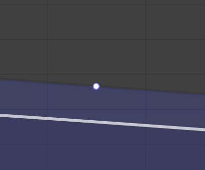
A point can have four statuses:
|
A mandatory point is drawn as yellow sphere. |
When the point is selected its color changes to red. |
|
If untouched the point is placed on the surface of the spline. A selected, untouched point is drawn as light blue. As soon as the point is moved by the operator it changes to touched. |
|
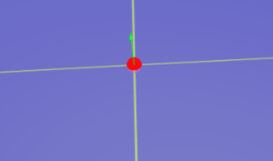
Point Selection
Clicking at the point selects the point and changes the parameter control.
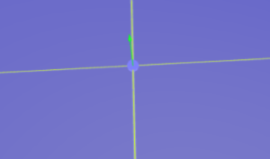
Line Selection
By hovering over a line, a red indicator is displayed. A new line can be inserted by SHIFT + Left-clicking on the line.
A line can be deleted by hovering over it, and press D on the keyboard.
A line can be moved, by hovering over it, and Left Mouse click on the line. In the Parameter Control, the zoom or focus value can then be modified (border lines can not be moved).
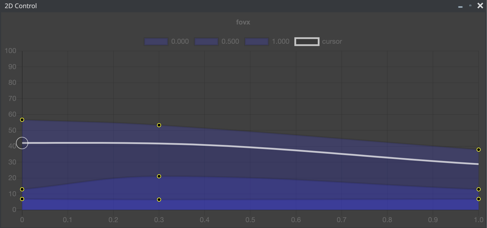
2D View
The 2D View is where the calibration should be done and values should be manipulated. Clicking into a point selects the point in 2D View and 3D View. Dragging the point manipulates the value. Using the mouse wheel, the user can zoom in and out (and increase the accuracy of the manipulation).
Navigation in the 2D View
-
Move: Click with the mouse in the 2D View, press SHIFT, keep the left Mouse Button pressed and move the mouse. This moves the diagram.
-
Zoom: Use the mouse wheel to zoom in and out.
|
Different States of Points |
|
|
|
|
|
|
|
The 2D view can be switched between Zoom and Focus mode (upper right)
Shortcut System
The lens file editor implements a shortcut system, which enables the user to operate the editor with keyboard shortcuts only.
|
Shortcut |
Change Parameter |
|
CTRL + 1 |
Field of View X |
|
CTRL + 2 |
Field of View Y |
|
CTRL + 3 |
K1 |
|
CTRL + 4 |
K2 |
|
CTRL + 5 |
Center X |
|
CTRL + 6 |
Center Y |
|
CTRL + 7 |
Nodal |
|
CTRL + 8 |
Depth of field |
|
Q |
Increases the value of the selected point for 1/1000th of it's actual value |
|
A |
Decreases the value of the selected point for 1/1000th of it's actual value |
|
W |
Increases the value of the selected point for 1/100th of it's actual value |
|
S |
Decreases the value of the selected point for 1/100th of it's actual value |
|
E |
Increases the value of the selected point for 1/10th of it's actual value |
|
D |
Decreases the value of the selected point for 1/10th of it's actual value |
|
ALT + Cursor Keys |
Moves selected point for one row or column |