
Tracking Hub Administrator Guide
Version 1.5 | Published April 05, 2022 ©
Configure Topology
This section details Topology configuration, which includes Tracking Systems, Rigs and Services.
At any time, view the properties of each configuration in the Configuration Panel.
The Topology configuration should be done in this order:
-
Configure a Tracking System.
-
Configure a Rig.
-
Configure a Service.
Configure a Tracking System
To Add and Configure a Tracking System
![]()
-
Click
 .
. -
Type a Name for the configuration.
-
Select which protocol to use to receive data from the tracking system:
Note: If changing the protocol of an already configured tracking system, the default configuration parameters for the new protocol are read by the system.
-
Select a connection type. Depending on the tracking system select the connection type:
-
Serial: If serial is selected, also select a Comport (in the Comport box, all available comports are shown). If the default baud rate is not used, enter the correct one in the baudrate field
-
TCP/IP: Type in the Host IP to use (it is possible to enter the port number as well).
-
UDP: Type in a Port number to use.
-
NDI: (For future use)
-
-
Right-click on the Tracking Systems box and select Connect (connect to the tracking system).
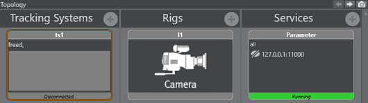
The Tracking Hub now connects to the selected Tracking System. Observe the colors on the bottom of the symbol:-
Green: Connection is done and data receiving in time.
-
Orange: If the color becomes orange, after a few seconds, connection is done and data receiving, but not in time.
-
Red: If the color becomes red, possible connection failure or data is not received.
-
-
Go to Configure a Rig.
Configure a Rig
-
Click
. -
Select from the list:
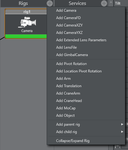
-
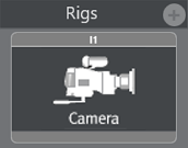
Add simple camera:
-
-
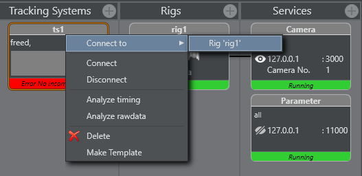
Right-click the Tracking System and select Connect to > Rig (Lattice).
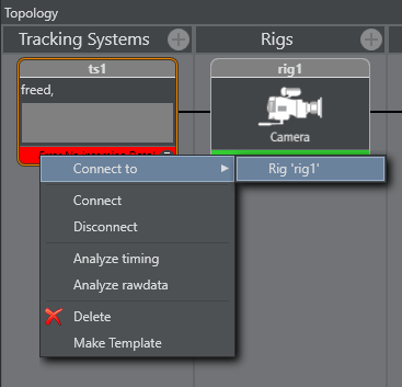
-
Set or change tracking parameters as required. When finished Click OK.
-
Go to Configure a Service.
Configure a Service
-
Click
.
-
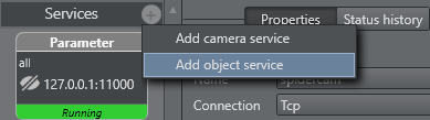
Select a Service:
-
Add camera service
-
Add object service
-
-
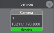
Click on the service icon in the Services panel.
-
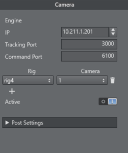
Configure the service in the Properties panel. When the service is added, one rig and one camera field are available. Pressing the + button add a rig/camera combination. It is possible to send any number of rigs to one Engine.
-
Rig: Type the name of the rig whose data should send to an Engine.
-
IP: IP address of the Viz Engine, which is to receive the tracking data.
-
Port: Port number for this connection (same port as configured in the Viz Engine configuration).
-
Cam.Number: Same as Viz Engine is expecting.
-
Mode: Not in use (default = 0).
-
Active: When checked the service is active, unchecked no data is sent to the Viz Engine.
-
-
Click Start in the Configure the Studio.
-
Click Save in the Configure the Studio.
Set a Delay
Set a delay (ms) before a tracking parameter is sent to the rig. Insert a delay, in frames, for tracking delay adjustment.
Insert this value in the first box. If you keep the second box empty, the value is set for all axes. If you choose an axis in the second box, the value is set for this axis only. Press the button after inserting.
Set an Offset
An offset (cm) can be added to a tracking parameter value, when passed to a rig, to correct positional rotation of a camera and, or an object

Values are set, if the field has lost its focus.
Analyze Time
Analyze Time is a visual representation of the tracking.
![]()
To Analyze Tracking System Time
-
Right-click on the Tracking System that is to be analyzed and select Analyze Timing.
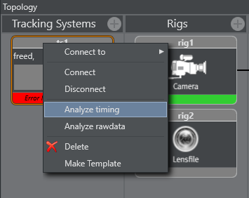
This adds a new element to the Services panel, called TrackingTiming. -
Click on the TrackingTiming Service element. In the Properties panel, make sure that:
-
The IP of the local PC is inserted, and
-
The service is set to Active.
-
To Analyze a Service Time
-
Right-click on the Service System that is to be analyzed and select Analyze Timing.
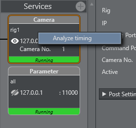
This adds a new element to the Services panel, called TrackingTiming. -
Click on the TrackingTiming Service element. In the Properties panel, make sure that:
-
The IP of the local PC is inserted, and
-
The service is set to Active.
-
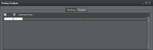
To View Timing Information
-
In the Configuration Panel, click the View Timing Analysis button
 . In a Timing panel with a correct data stream:
-
Purple line: Shows the time when the Tracking Hub has inserted a data package from the tracking system into the data pool.
-
Green line: Shows the time when the communication part of the Tracking Hub starts to read from the data pool.
-
Red Dot: Indicates data sent to a Viz Engine has stopped.
Upper Section
In the upper section, the first line is the timing of live tracking data.
These timestamps are shown:
-
Sync:
-
Start RX: Start time, when data is received from the tracking system.
-
End RX: End time, when data stops from the tracking system.
-
Start Ins: Start time, when Tracking Hub inserts received data into the parameter pool.
-
End Ins: End time, when Tracking Hub has finalized inserting data.
-
-
Orange Dot: Sync Timestamp
-
Blue: The time between Start RX and End RX
Note: The time between Start RX and End RX can be very short and thus almost invisible if network communication is in use.
-
Purple Line: The time between Start Ins and End Ins
-
Line 2: Shows when the live tracking data is processed and sent to the Viz Engine.
-
Start Calc: The start time. When tracking data is calculated and prepared for a Viz Engine, this time is defined from send delay. After this delay has passed the Tracking Hub starts with this procedure for calculation and sending data.
-
End Calc: The end time. When tracking data preparation is finished.
-
End Send: Time when data has been send to the Viz Engine.
-
Green Line: Time between Start Calc and End Calc.
-
Red Dot: End Send Timestamp
Lower Section
The lower part shows the last ten second history of the timing. Three timestamps are shown.
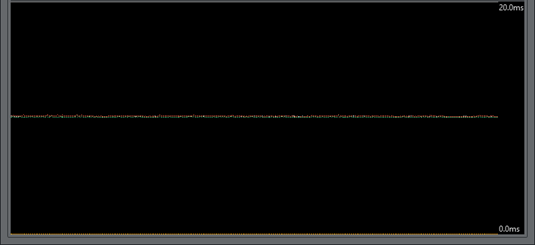
Note: Only three timestamps are shown to make the recognition of the timing behavior easier.
-
End Ins: As time, when receiving is finished, shown in purple (1).
-
Start Calc: When data processing starts, shown in green (2).
-
End Send: When Tracking Hub work is finished for this field, shown in red (3).
To get the optimal timing, the Start Calc time must be later than the End Ins time, for every field. To achieve this, the send delay has to be adjusted correctly. The white line shows the delay. This line should be the absolute border between End Ins (purple line) and Start Calc (green line). To change the delay, use drag and drop to move the white line. If the delay can not be adjusted correctly, this can be for several reasons, for example, tracking data is received too late.
Note: This is not too bad, but keep in mind, that this result is in a tracking delay of one field.
This doesn't matter so much, because in normal production you need more the one field tracking delay.
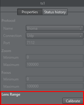
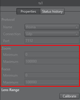
Lens Range Calibration
This section details how to calibrate the Lens Range.
-
First, collect the minimum and maximum Values of Zoom and Focus:
-
In the Tracking System properties panel, click the Calibration button:
-
Go to the broadcast camera and move Zoom and Focus to their upper and back to their lower limits, at least two times. Observe that the system receives the full set of data:
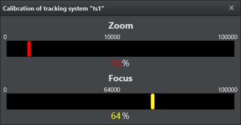
To check if the calculation is correct, the corresponding Min/Max values, of the Lens encoder, are shown in the Zoom and Focus fields.
-
Re-using Lens Ranges from Older Version Lens Files
The lens range in Tracking Hub is from 0 to 1. For setups used with software preceding the Tracking Hub, such as Viz IO, the lens files may have used lens ranges specified slightly differently, such as from 0.01 to 0.99. The Tracking Hub is capable of adapting to such a lens range. To achieve this, the lenserange parameter in the studio configuration file needs to be entered manually.
Warning: Editing the configuration manually can lead to software malfunction, and should only be done by qualified professionals.
Modify a Rig
If a Tracking System parameter does not equal a Viz Engine parameter, a Viz Engine parameter can be modified to adapt to the Tracking System parameter.
To modify a Rig
-
Right-click on a Tracking System. Select Connect to a rig.
-
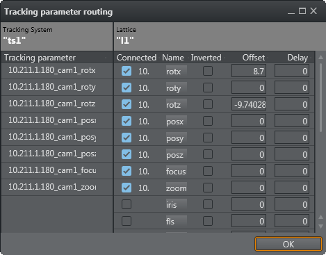
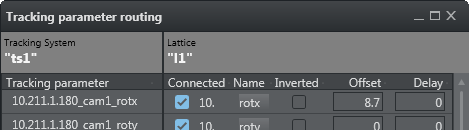
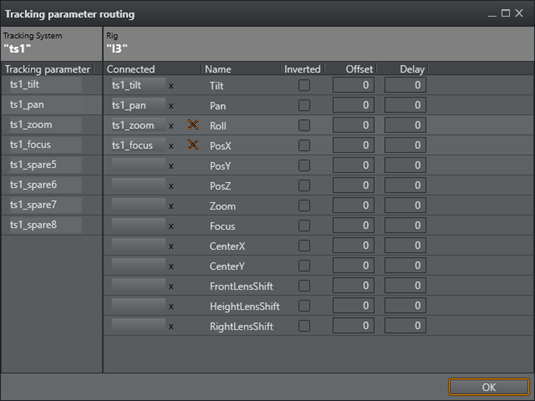
The Tracking parameter routing window opens.
-
The Tracking System panel shows all the parameters that can be tracked.
-
The Rig panel shows the Rig connections.
-
-
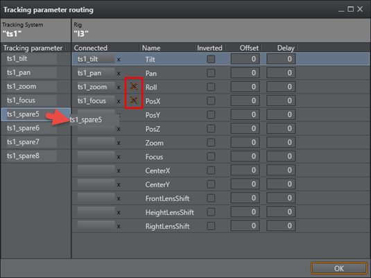
If a Tracking System parameter does not equal a Viz Engine parameter, a Viz Engine parameter can be modified to adapt to the Tracking System parameter. Click on a Viz Engine parameter and drag to its new position, as required. If a red cross shows, after a parameter has been modified, it means that the connection is still valid, but the connection is now a cross-over connection and not a straight one.
-
In the Offset column, define an offset to each parameter. The values are given in centimeters or degrees (value with dot). The values are stored when the field loses focus.
-
In the Delay column, enter how many fields sending of the parameter should be delayed.
-
Click on a box under Connected to connect a parameter through the rig.
-
Click OK.
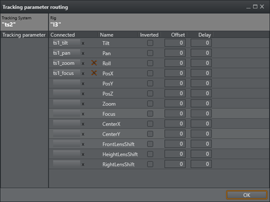
No Tracking Parameters
If the Tracking parameter panel empty, there are no tracking parameters delivered from the tracking system.
-
Check what the icon of the tracking system shows (disconnected or connected, color, etc.).
-
Check all connectors until the required connections show in the Tracking Parameters panel.
-
Go to To Modify a Rig.