Basic Camera
The rig object Basic Camera has to be attached at the end of every rig structure. In this rig object is the most basic and most often used parameters required for exact tracking. This section shows how the Tracking Hub needs to place the idealized OpenGL point camera to create an approximation of the physical studio camera.
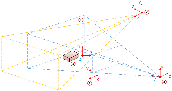
| Item | Description |
|---|---|
|
1 |
Clip space |
|
2 |
Light Space |
|
3 |
Camera Space |
|
4 |
Image Space |
|
5 |
Object Space |
By default, the OpenGL camera is a point in space. All transformations (perspective and model view) are linear. It does not matter how much the zoom is increased in the perspective, or how near the camera is to an object in the model view transformation, a straight line in the model space will be a straight line in the image projection. When the camera is rotated it will rotate around its position.
Nodal Point
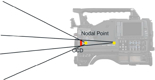
Let us assume the OpenGL camera is placed on the charge-coupled device (CCD) of the camera body.
In the image, above, it completely depends on the field of view, where the light rays reflected from an object conjure to a point and create a sharp picture on the CCD. For sports, where the real camera is far away from the watched objects (we assume distances of more than 10 meters), there is no influence from the adjusted focus. Therefore in the image above we only observe the zoom effects on the nodal point of the objects watched.
Zooming in and out, causes the light rays, going through the lens, to conjure on a moving point behind the lens. In our Viz Virtual Studio software, we call this point the Nodal Point, and this point marks the position where we have to place our idealized OpenGL camera. The Nodal Point is defined during lens calibration, which is still happening in the Viz Engine. Therefore it is not an error, if you zoom in and out, and the position of the camera is moving towards and away from the Look-At direction of the camera. This is intended and must be done to provide an accurate result.
Note: Currently the Nodal Point comes from the lens file only.
Center Shift
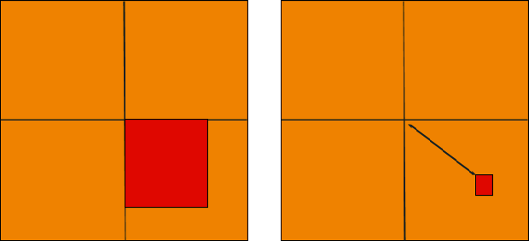
Whenever one object is mounted to another, the connection will not be 100% straight. This is true for camera bodies and lenses as well. There will always be an offset angle between the camera body and the lens. Therefore the light does not come completely straight to the CCD.
In the Viz Virtual Studio software this effect is called the Center Shift. Every lens shows its own center shift, which is much smaller than the mount error center shift and can be ignored most of the time. The most visible Center Shift is caused by the mount and becomes more and more visible/evident as the mount connection between the camera body and the lens is damaged.
Note: Currently Center Shift can be corrected in the lens file only.
Mounting Offsets
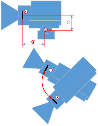
| Item | Description |
|---|---|
|
1 |
CCD |
|
2 |
Height Lens Shift |
|
3 |
Tilt Axis |
|
4 |
Front Layer |