Rig Objects
Rig objects (sometimes called Lattice objects) are used to represent geometry. The Tracking Hub separates tracking from geometry. All tracked parameters (Axis) are, as described in the Parameters section, collected in the Parameter Pool.
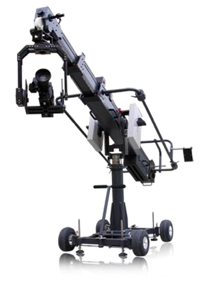
Rig objects are built from hierarchical arranged sub elements where every sub element represents a mechanical or optical part of a tracked camera and its mechanical rigging.
Currently the following rig elements are covered:
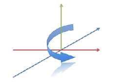
Pivot Rotation
Rotates the coordinate system of a rig around a free definable point in space. The camera Rig is bound to the pivot point in a parent child relationship.
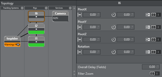
PivotX, PivotY and PivotZ defines the location of where the rotation will take place. Rotation specifies the rotation in degrees around the Y Axis of the pivot point.
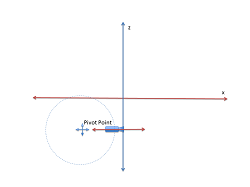
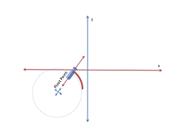
After the rotation the coordinate system of the Rig is rotated around the Pivot Point. This is useful if, for example, a rail tracker needs to be adjusted in angle and offset to a studio coordinate system.
Location Pivot Rotation
The location pivot rotation rig is similar to the Pivot Rotation. The difference is, that this rig takes the pivot point coordinates from the child camera’s position offset, which is attached to the camera position.
This Rig accepts only a rotation angle as the position is taken from the child position offsets.
Camera Rig
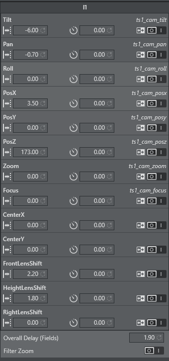
The Camera Rig represents the simplest camera known in the Tracking Hub. It holds the rotation and position parameters of a real camera in the studio. Zoom and Focus (in raw format coming from an encoder) and the Front, Height and Right lens shifts which are coming from the mount of the camera.
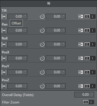
Position and Rotation
Tilt, Pan and Roll defining the rotation of the camera around the X,Y and Z Axis.
PosX, PosY and PosZ defines the position of the camera in space. Every one of these values might be tracked. In the case of a Pan/Tilt camera head, which does not provide position information, the position can be adjusted in the offset values.
Zoom and Focus
Zoom and Focus are coming from the Lens encoders (whether internal or external). In the system and in Viz Engine these values are always normalized and goes from 0 to 1. Therefore it is most important that the Lens Ranges are calibrated correctly in the tracking system.
Center Shift
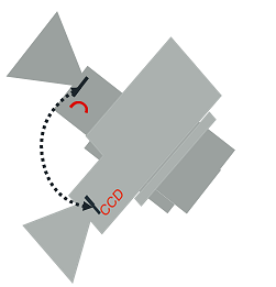
Whenever you mount a lens to a camera body, the connection will never be 100% the same every time; hence, there will always be an offset between the camera body and the lens which will shift the angle of the light onto to charge-coupled device (CCD). In the Viz Virtual Studio software this effect is called the Center Shift.
Note that every lens shows its own center shift and can for the most part be ignored as it’s much smaller than the center shift caused when mounting the lens to the camera body. The most visible center shift is caused by the actual mounting of the lens and is more and more visible as the mount connection between the camera body and the lens is damaged/worn.
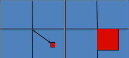
In order to calibrate the center shift, the Camera Rig handles the CenterX and CenterY offsets the following way: Completely zoomed out the full offset will be applied and sent to the Viz Engine. As more zoomed in these values go in zero direction until they reach absolute zero when completely zoomed in. It is absolutely necessary to calibrate this center-shift to get an acceptable tracking result. Whenever you see a movement of virtual objects when zooming in and out, you will have to check if the center shift has changed.
Note: Always check the center shift after mounting your lens to the camera body!
To calibrate the center shift, follow the algorithm below:
-
Reset the CenterX and CenterY values to zero.
-
Look for a corner or easy to identify point in the camera view.
-
Enable the Center Shift Cross in Viz Artist, see Scene Settings > Virtual Studio.
-
Zoom completely in to this point and adjust focus. This is also a good point in time to check the back focus of the camera.
-
Pan and tilt the camera until the corner or point aligns with the Center Shift Cross.
-
Zoom out completely and you will see that the point slides away from the center.
-
Adjust the CenterX and CenterY values until the corner or point aligns with the Center Shift Cross again.
-
Zoom out completely. If the Center Shift Cross is no longer in the corner or point, repeat from step 5.
Note: Repeat the steps until the Center Shift Cross is on the corner or point at all times. After two or three iterations this is usually the case.
Mounting Offsets
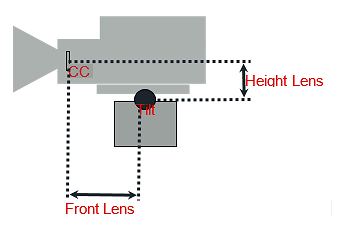
In order to get an acceptable result we need to know the exact position of the camera’s charge-coupled device (CCD) position. The CCD is (after the optical nodal point) the position of the Viz Engine remote camera.
Not every tracking system gives that position. More likely, the position of the last rotation axis on the mechanical head is given, which in most cases is the tilt axis. If the send position is not clear, you will have to contact the vendor of the tracking system.
After mounting a camera to a head there will always be offsets between the tracked point and the CCD of the camera. Many cameras have a mark on their body which marks the position of the CCD. If no mark is visible, you can assume that the CCD is 2 cm behind the mounting point of the lens.
In Tracking Hub we know three mounting offsets. The FrontLensShift, HeightLensShift and the RightLensShift. The following drawings show the Front and Height Lens Shift and how these values change the behavior of the CCD.
Extended Lens Parameters Rig
This rig holds parameters, which are rarely used and delivered by TrackMen and Libero only.
Object Rig
The object rig is used to position an object in Viz Engine with the use of shared memory and the object service. It can be used to mask out pedestals, which would be in view of other cameras or to track objects with the Motion Analysis tracking system. Pan/Tilt/Roll are the rotation angles of the object and PosX, PosY and PosZ are the position in centimeters (cm). Connected to an Object-Service the coordinates will be sent to Viz Engine and can be applied to any objects in the Viz Artist scene tree by a script.