Viz Mosart is capable of controlling video servers from many different manufacturers. Although the end result is the same, each video server type operates in a slightly different way.
It is essential that the correct settings are defined in AV Automation for Viz Mosart to effectively and correctly control your video server. You reach these settings with
AVAutomation > Devices > Properties> Video Servers tab.
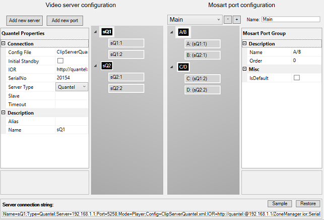
The left side (Video server configuration) presents details of the physical video servers and their ports.
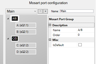
The example above presents a Quantel server (as selected from the Server Type drop-down menu), sQ1, and one other server (sQ2), which could also be a Quantel server.
Server sQ1 has 2 ports defined, sQ1:1 + sQ1:2.
Server sQ2 has 2 ports defined, sQ2:1 + sQ2:2.
This is described in Working with Video Server Configurations and Working with Servers and Ports.
The right side (Mosart port configuration) presents details of the virtual connection within Viz Mosart, with salvos, virtual ports, virtual port groups and assignments of physical server ports (as defined on the left side) to virtual ports. These concepts are presented below.
This is described in Working with Mosart Port Configuration.
This rest of this section contains the following topics, presented according to the configuration menu illustrated above, from left to right:
Video Server Configurations
You can add or remove video servers to your Viz Mosart system, and modify the configuration of existing hardware.
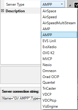
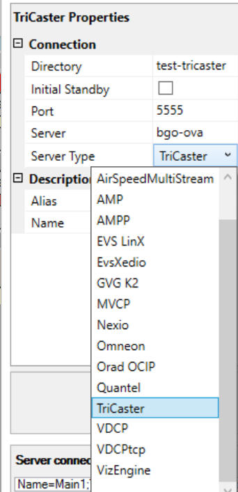
Viz Mosart supports a wide range of video servers. These appear in the Server Type drop-down menu.
Note: Only compatible combinations of Media Administrator and AV Automation drivers can be defined. Please contact Vizrt Support for further details.
The Name property links the selected video server to a Media Administrator properties line.
For an explanation of the various configuration properties, please refer to the specific video server model, as presented in Video Server Properties below.
After configuration, restart Media Administrator and AV Automation, and ensure that the GUI is connected to the required server.
Verify that all indicator lights for the selected video server go green.
Tip: If you do not get green lights, and you see a message similar to this in the Mosart log: Failed connecting to video server K2: The source was not found, but some or all event logs could not be searched.Inaccessible logs: Security.
you can try to start AVAutomation as Administrator. This is a known issue with Grass Valley servers. More info here: http://www.gvgdevelopers.com/concrete/apis/appserver_api/windows/
Video Server Properties
Here are some guidelines for common video servers that Viz Mosart can work with.
Common Settings
In most cases, the settings below are always required:
Initial Standby: If selected, the server is forced to start in Standby mode.
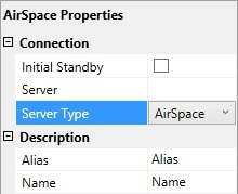
Server Type: Name of supported video server. For example, AirSpace, AirSpeed, EVS LinX, Orad OCIP.
Alias: Defines the name of the server to display in the Viz Mosart GUI and Timing Display.
Name: Internal name of the server, displayed in AV Automation
The above settings are typical for
AirSpace, AirSpeed, EVS LinX, EVS Xedio, OradOcip video servers.
Some common video server properties are summarized below:
AirSpeed MultiStream
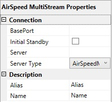
BasePort: The first port Viz Mosart uses to communicate with the AirSpeed MultiStream server.
Default:59451Server: Defines the hostname or IP address of the video server.
AMP
Please refer to Common Settings above. In addition, there is
Port: The default is 3811. Do not change this unless you know what you are doing.
Server: Defines the hostname or IP address of the video server.
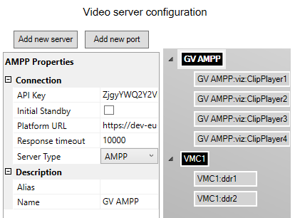
Grass Valley AMPP
Please refer to Common Settings above. In addition, there is
Platform URL: The AMPP Platform URL. This URL should look like https://<region>.cloud.grassvalley.com
API Key: An API key allowing you to connect to the AMPP Platform for sending/receiving AMPP Control messages
Response timeout: Timeout in milliseconds to wait for the responses from the server. Default 1000
Grass Valley K2
Connection to K2 is initialized with a ping (ICMP) from Mosart to the server to confirm the connection. Then it uses port 3811 to communicate with the K2 server. Both must be open for Mosart to be able to connect.
Manus Admin uses a separate port when it connects: 49171 (a range is OK. Use 49168-49172)
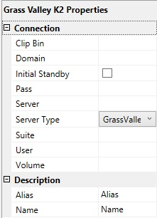
Clip Bin: This value, together with that of Volume (see below), defines the default server location of clips to be played. This default location is used only when the location is not provided by other means. (In particular, it is not used when the setting IgnoreBin (in Media Administrator) is true for this server.) The value of Clip Bin should designate a bin in the volume designated by the value of the Volume setting.
Domain: The domain as part of the user credentials.
Pass: The password as part of the user credentials.
Suite: Arbitrary value. However, follow these guidelines:
For each K2 server, two or even three unique Suite values must be used:
First, the values for Media Administrator and AV Automation must be different.
Second, in a redundancy setup with Main and Backup Mosart server, the two values for Media Administrator must be different.
Note: In this constellation, both Main and Backup AV Automation should use the same value, different from the two Media Administrator values.
User: The username as part of the user credentials.
Volume: This value, together with that of Clip Bin (see above), defines the default server location of clips to be played. This default location is used only when the location is not provided by other means. (In particular, it is not used when the setting IgnoreBin (in Media Administrator) is true for this server.) The value of Volume should designate a server volume.
Server: Defines the hostname or IP address of the video server.
Nexio
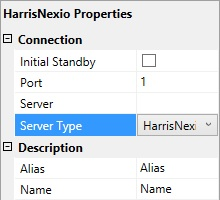
Port: TCP/IP communication port to the Nexio server.
Server: Defines the hostname or IP address of the video server.
MVCP
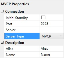
Port: TCP/IP communication port to the MVCP server.
Server: Defines the hostname or IP address of the video server.
Omneon
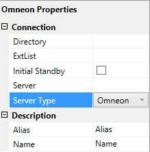
Directory: Defines the directory where the clips are stored.
ExtList: The list of valid file extensions used when listing and querying files on the server. The list is period separated and case sensitive.
Server: Defines the hostname or IP address of the video server.
Quantel
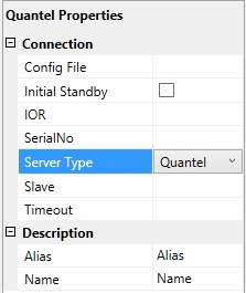
Config File: The path to the XML configuration file used to define the Viz Mosart - Quantel communication.
IOR: The HTTP link including hostname or IP address to the IOR resource on the Quantel ISA manager. Example: http://192.168.100.50:2096/ZoneManager.ior
SerialNo: The serial number of the Quantel playout server.
Slave: The hostname or IP address of the slave/backup IOR.
Timeout: Timeout value for requests from Viz Mosart to ISA manager. If the request exceeds this timeout the server connection is reinitialized. Setting a value here should only be needed for sites experiencing issues with the Quantel connections. Leaving a blank value uses the default timeout.
Server: Defines the hostname or IP address of the video server.
Recording with Quantel Devices
Quantel requires a duration when preparing a recording. This duration can be set the following ways:
As part of a template: Specified using markin and markout properties.
As part of a keyboard shortcut: Specified by trailing the
ClipNameproperty with [,duration]. Similar to the examples under the general section Controlling Video Servers from Mosart above.As part of template control command: Specified as part of the Parameter property. Again, see the general section above.
TriCaster
The Vizrt TriCaster uses the TriCaster protocol (previously named vizrt-ips protocol).
Directory: The TriCaster directory used for clips path.
Initial Standby: If selected, the server is forced to start in Standby mode.
Port: TCP/IP communication port to the TriCaster (Default: 5951).
Server: Defines the hostname or IP address of the TriCaster.
Server Type: TriCaster
VDCP
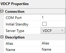
COM Port: The COM port connected to the VDCP video server.
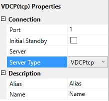
Port: The TCP/IP communication port connected to the VDCP video server.
Server: Defines the hostname or IP address of the video server.
Viz Engine
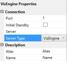
Port: The TCP/IP communication port connected to the Viz Engine video server.
Server: Defines the hostname or IP address of the video server.
Video Server Port Properties
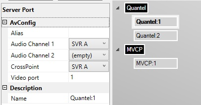
Alias: Defines the name of the server to display in the Viz Mosart
Audio Channel 1: The audio channel 1 for the selected video port.
Audio Channel 2: The audio channel 2 for the selected video port.
CrossPoint: The video crosspoint for the selected video port.
Video port: The actual port name/number on the video server. Please refer to the documentation of your video server for information on how to find these.
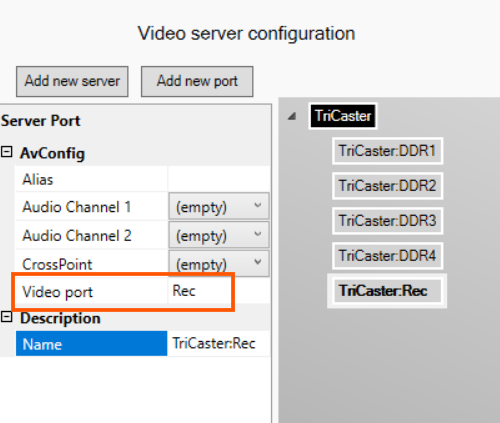
For the Server Type TriCaster, any recording port must have a 'Video port' of the form recN, where N is a number.
Name
Working with Servers and Ports
To Add a Server
Click the Add new server button
In the Properties pane on the left, select from Server Type and add additional information such as Port and Server host.
To Remove a Server
In the Video Server Configuration tree, right-click a server node and select Remove.
To Add a Port
In the Video Server Configuration tree, select a server node
Click the Add new port button, or right-click the server node and select Add new port
In the property editor on the left, enter the port information.
To Remove a Port
In the Video Server Configuration tree, right-click a port node and select Remove.
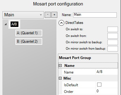
Mosart Port Configurations
The right-hand part of the Video Servers tab (titled 'Mosart port configuration', shown in the screenshot below) has three parts:
the salvo part (in the screenshot the first ‘line', starting and ending with 'Main’, and also the DirectTakes panel with four text boxes and labels)
a tree structure showing virtual ports and virtual port groups (the bulk of the left-hand side of the screenshot)
a panel showing the details of the virtual port or the virtual port group selected ('Mosart Port Group' in the screenshot).
A salvo is a particular setup of servers and ports. There will always exist at least one salvo. If several salvos are defined, these will usually involve different sets of servers and/or ports, and the user will be able to switch from the active salvo to some other salvo. This will involve, among other things, disconnecting from servers that will not be used in the salvo switched to, and connecting to servers that are to be used now. This will be discussed later.
Working with Mosart Port Configurations
The tree structure shows the virtual ports and virtual port groups defined. (These are the same in all salvos.) Visually (in the tree structure), the groups are black, and the ports are grey (and indented). A virtual port may have one or two server ports linked to it. (If it has two server ports linked to it, the two are mirrored. Mirroring will be discussed later.) A virtual port group is, as the name indicates, a group of virtual ports. Such a group may be used for A/B roll (playout of clips on alternate ports). Both virtual port groups and individual virtual ports are available for selection in the Template editor.
To add a virtual port group
Right-click in the Mosart Port Configuration tree (not on a node) and select either:
Add virtual ripple group to add a new virtual ripple group. The default ripple group names are A/B, C/D, E/F etc.
Add virtual preview group to add a new green virtual preview group to be used for preview ports. The default preview group name is P.
Add virtual recording group to add a new red virtual recording group to be used for recording ports. The default recording group name is Rec .
The virtual port group is added to all salvos.
You can edit or rename the selected group using the Properties Editor on the right.
To remove a virtual port group
You can remove a virtual ripple group, preview group or recording group.
In the Mosart Port Configuration tree, right-click any ripple/preview/recording group and select Remove group <name>.
Alternatively, select a group and press the Delete key.When prompted, click Yes. The group will then be removed from all salvos. (If you click No, nothing will happen.)
To add a virtual port
In the Mosart Port Configuration tree, right-click any group and select Add virtual port.
If the port was added to a preview group, the added port will be a preview port with default name P. If the port was added to a recording group, the added port will be a recording port with default name Rec.
Note: Do not change the name Rec!
If the port was added to a virtual ripple group, the added port will be a playout port. The name will be the first unused (for this purpose) (upper-case) Latin letter (A, …, Z).
Note: There is no relationship between the port name and the group name. E.g., group A/B may have ports C and D, and vice versa.
To remove a virtual port
In the Mosart Port Configuration tree, right-click any virtual port and select Remove <name>. Alternatively, select a port and press the Delete key.
When prompted, click Yes. The port will then be removed from all salvos. (If you click No, nothing will happen.)
To link a server port to a virtual port
You can link a server port to a virtual port:
Select the server port (in the left-hand, Video server configuration part) you want to link, and drag it to the virtual port (in the right-hand Mosart port configuration part) to which you want to link it.
Note: If the virtual port is a recording port (in the recording group), the server port to link must also be a recording port: The physical server must have recording capabilities (and the chosen Server Type must allow for recording).
To inspect or change the details of a virtual port group
Select a virtual port group in the tree structure:
(Here, A/B is selected.) These details are available:
Name: The name of the virtual port group. This name is displayed in the will be among the options in the SERVERCHANNEL drop-down in the Videoserver Device properties in the Template editor.
IsDefault: Enable to set the default and preferred video port group for assets residing on multiple systems.
Order: Used by the Media Router only. (See the documentation of the Media Router.) If a Media Router is not used, this value can be left at the default 0.
To inspect or change the details of a virtual port
Select a virtual port in the tree structure:
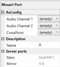
(Here, A is selected.) These details are available:
Audio Channel 1: The virtual audio fader 1 for the selected video port. If nothing is selected here, the audio fader from the physical port is used. Default: Empty
Audio Channel 2: The virtual audio fader 2 for the selected video port. If nothing is selected here, the audio fader from the physical port is used. Default: Empty
CrossPoint: The virtual video crosspoint for the selected video port. If nothing is selected here, the video crosspoint from the physical port is used. Default: Empty
Note: In most cases, the three fields above should be left at their default '(empty)'. Then the fader/crosspoint from the physical port will be used. Changing to a specific fader/crosspoint will override this. Do this only if you know what you are doing.
Name: The name of the virtual port. This name will be among the options in the SERVERCHANNEL drop-down in the Videoserver Device properties in the Template editor.
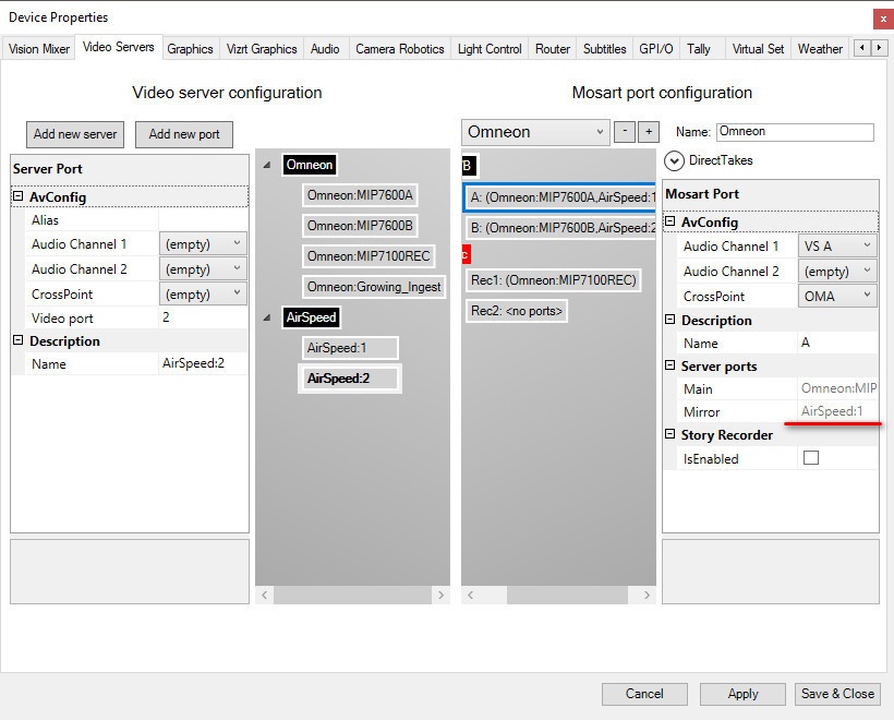
Main: Auto-generated display name of the linked server port (as explained in To link a server port to a virtual port above), if any.
Mirror: Auto-generated display name of the mirror server port. (This refers to mirroring, to be explained shortly.)
Mirroring
Mirroring refers to having two (instead of one) physical ports linked to each virtual port. (Only two ports may be mirrored.) The two ports will have the same state. E.g., they will both have the same clip cued, or they will both play the same clip (and at the same position). The intended use of this feature is to be a redundancy setup. At start-up, the ‘Main' ports is active, i.e., its outputs (video and audio) are routed through the mixers, whereas the outputs of the 'Mirror' ports are not. The Mosart operator may, especially if there is a problem with a video server linked to a Main port, switch to the 'Mirror’ ports. (There are functions for this both in the Viz Mosart GUI and in AV Automation.) Then the role of the ‘Main' and the 'Mirror' ports are swapped: Now the outputs of the Mirror ports are routed through the mixers, whereas the outputs of the Main ports are not. (The problem with the video server should then be fixed, so that the operator may switch back to Main at some point.)
For this to work as intended, no physical server should participate in both Main and Mirror. I.e., if a physical server has at least one port being the Main port for some virtual port, it should not have a port being the Mirror port for some virtual port.
This method differs from a the use of Main and Backup salvos, to be described later.
To link a second server port to a virtual port for mirroring
It is assumed that you have at least one physical video server and at least two physical ports.
Link one server port to a virtual port as described in To link a server port to a virtual port. Then the situation may be as in the screenshot below. (Here server port Omneon:MIP7600A has been linked to virtual port A.)
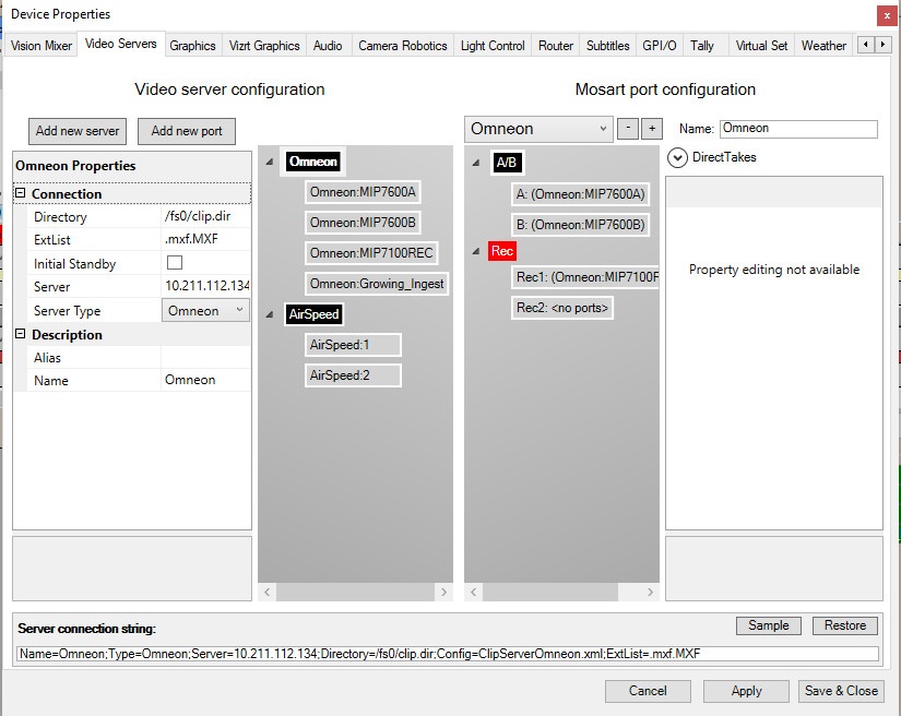
Link another server port to the same virtual port. (Referring to the general description of the Mirroring feature above, the two server ports linked to a virtual port should reside on different servers.) In the screenshot below, server port Airspeed:1 is about to be linked to virtual port A.
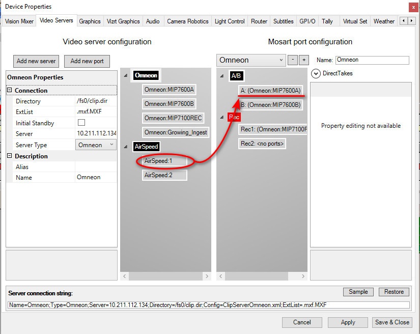
The text in the virtual port node in the tree will change to reflect that now two physical ports have been linked to it..
Click on the virtual port to verify that the server port from step 2 is now listed as a mirror. In the screenshot below, server port Airspeed:1 is indeed the Mirror linked to virtual port A.
Repeat for other virtual ports as needed.
Click Apply, then Save & Close.
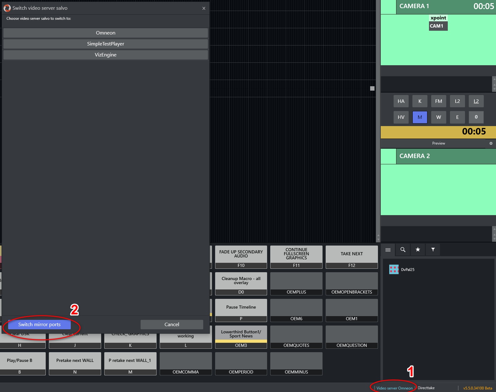
Verify that you can now switch between mirror ports
Either with the Mirror button in Av Automation
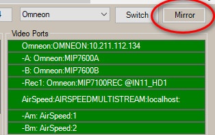
or
In the Mosart GUI.
To clear server links in a virtual port
Right-click the virtual port and select Clear links.
To clear the server links from a virtual port group
Right-click the virtual port group and select Clear all links.
Working with Salvos
A salvo is a particular setup of servers and ports. All salvos have the exact same virtual ports and port groups. Salvos differ only in the assignments of physical ports to virtual ports. There will always exist at least one salvo. If several salvos are defined, these will usually involve different sets of servers and/or ports. At any time, one salvo will be active. The user will be able to switch from the active salvo to some other salvo (which will then become active). This will involve, among other things, disconnecting from servers that will not be used in the salvo switched to, and connecting to servers that are to be used now.
Note: Salvos are distinct from Mirroring. When using Mirroring, both the Main and the Mirror ports are connected all the time.
There are several use cases for salvos:
Redundancy: To lessen the effect of video server malfunctions, Main and Backup salvos may be defined, presumably using different servers.
Different needs for different shows, or even within the same show (for instance, sports and news).
Note: It is recommended that the default Main and Backup salvos are not renamed.
The configuration of salvos are done in the upper line of ‘Mosart port configuration', and also in the 'DirectTakes’ panel:
The available UI elements are
Drop-down with the configured salvos, used for selecting a salvo for configuration or deletion. (If another salvo is selected, this salvo will become active. However, this is not the standard way of switching salvos during normal operation. The standard method is using the salvo controls in the main window in AV Automation.)
 button for deleting the selected salvo
 button for adding a salvo
Name: The name of the selected salvo.
Direct Takes
On switch to: The Recall Nr (see Template Properties) of the direct take template that should be taken when switching to this video server salvo.
On switch from: The Recall Nr of the direct take template that should be taken when switching from this video server salvo.
On mirror switch to backup: The Recall Nr of the direct take template that should be taken when switching to a backup server using this video server salvo.
On mirror switch from backup: The Recall Nr of the direct take template that should be taken when switching from a backup server using this video server salvo.
To add a salvo
Click the
button.
A new salvo is created and automatically selected in the drop-down (and also becomes the active salvo). Please note that there are no linking of physical ports to virtual ports. You may want to make such links, and also to change the name of the new salvo.
To remove a salvo
Select the salvo to remove in the drop-down.
Click the
button.
The selected salvo is removed. Another salvo is automatically selected in the drop-down (and also becomes the active salvo).
To modify a salvo
Click the drop down box above the Mosart Port Configuration tree and select the salvo you want to edit.
Rename the selected salvo in the Name textbox and/or
Add/change port links as described above.
Video Server TriCaster Setup Example
As an example of a typical video server workflow, this scenario describes how Viz Mosart can control the clip playout and the recording of the output from a TriCaster video mixer.
Configure the TriCaster audio and video channels in Mosart
Before configuring TriCaster as a video server in Viz Mosart, ensure that the audio and video inputs are correctly mapped in Viz Mosart’s A/V Setup.
Navigate to Av Automation > Devices > AV Setup > Audio config and configure the audio inputs as configured on TriCaster.
The input indexes can be taken by accessing TriCaster over REST API:
http://<TriCaster_host>/v1/dictionary?key=audiomixer
For audio, the indexes are 1-based, so add +1 to the number found in the the request response: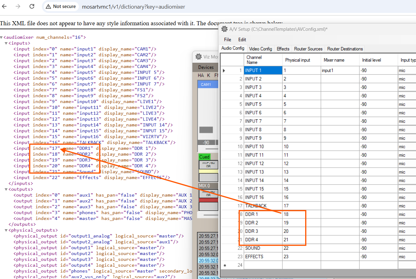
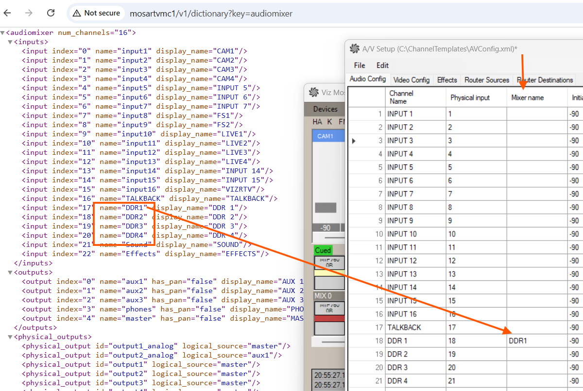
Alternatively, the input name can be mapped to the Mixer name column in A/V Setup in which case the Physical input value is not relevant, but must be filled to a number unique within the values from that column.
Navigate to AV Automation > Devices > AV Setup > Video config.
Add the crosspoint mapping video server ports as configured on the TriCaster.
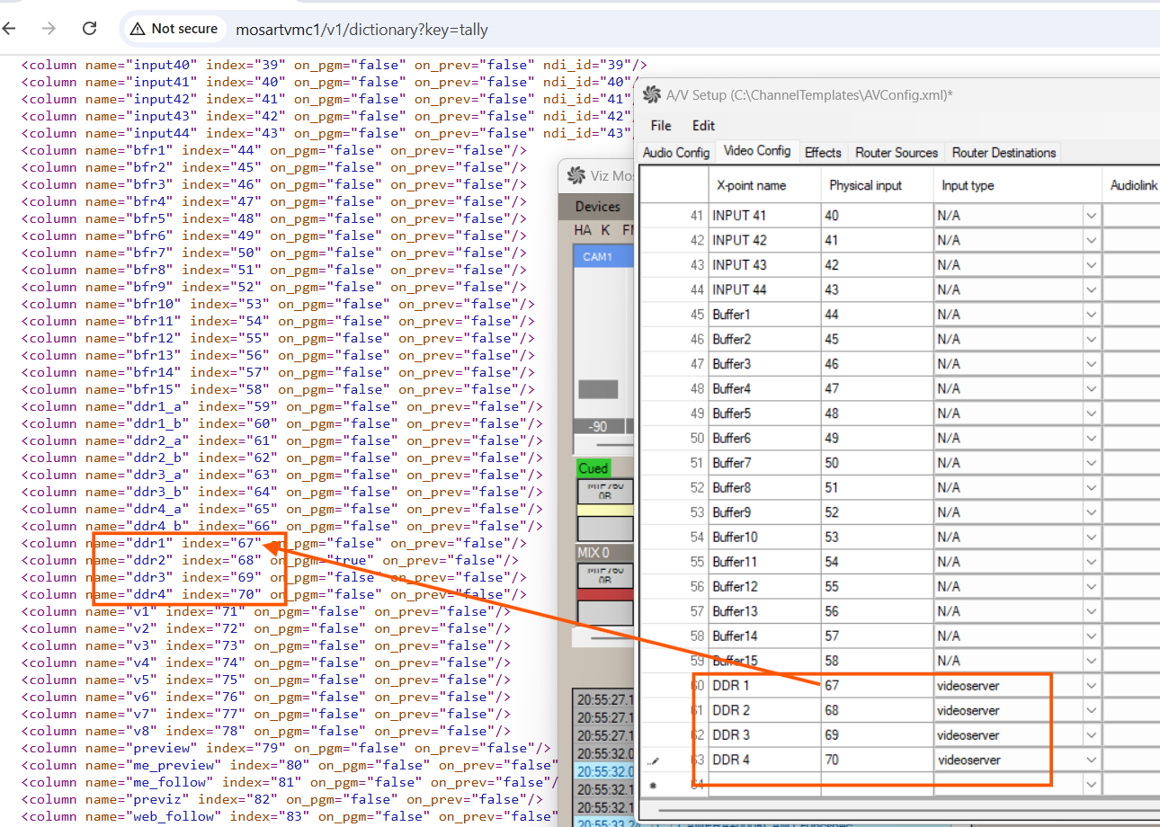
The input indexes can be taken by accessing TriCaster over REST API:
http://<TriCaster_host>/v1/dictionary?key=tally
Configure TriCaster as video server
Navigate to AV Automation > Devices > Properties > Video Servers.
Under Video server configuration on the left side, click Add new server
If not in focus, click on the newly created black box, New server.
From the Server Type drop-down menu, select TriCaster.
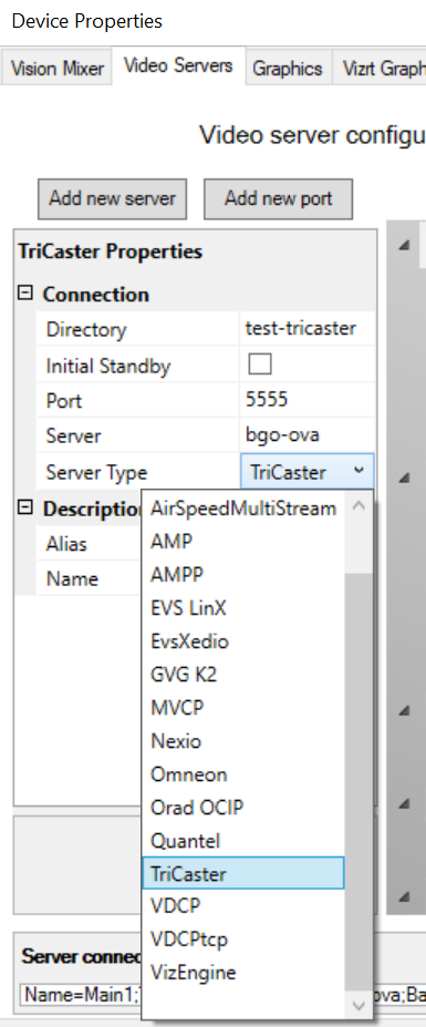
Name the server appropriately by filling in Name.
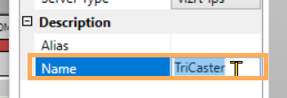
Click on the black box (see below) and configure the following properties for the server:
Server: http://<TriCaster_host> as IP number.
Directory: {volume}:/Sessions/{session name}/Clips/Import
See To find session name below.
Extension: let it empty (when Media Service is used, no extension is needed).
Note: The clip id can be given from NRCS without extension.
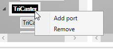
Name: Any meaningful name. Make sure the name is the same as the connection string provided in Media Admin.Right-click the black box and add a port corresponding to each DDR port configured in TriCaster, DDR1, DDR2 etc.
For each server port added on the left side, configure:
Audio channel 1: Select the audio channel configured in A/V Setup > Audio Config that is associated with the first mono channel of the stereo pair for playback from a DDR port in TriCaster.
Audio channel 2: If applicable, select the audio channel in A/V Setup > Audio Config that is associated with the second mono channel of the stereo pair for playback from a DDR port in TriCaster.
CrossPoint: Select the video channel configured in A/V Setup > Video Config that is associated with a playout ports in TriCaster.
Video port: The physical port names as configured in TriCaster, DDR1, DDR2, DDR3 etc.
Name: Any meaningful name.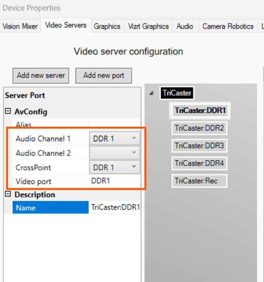
Add a recording port where the physical name must start with Rec:
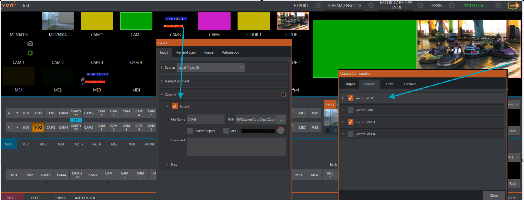
From Viz Mosart, you can start the global TriCaster recorder, triggering the recording of any configured recording sources.
TriCaster offers two types of recording options:
MIX Output Recording: Records one of the four MIX outputs (PGM or other selected outputs).
ISORecorder: Records specific input sources configured for isolated recording.
When recording is triggered from Mosart, any MIX output or ISORecorder inputs that have been enabled for recording in TriCaster will automatically start recording.
The recorded files are stored based on the recording configuration set in TriCaster’s record settings.
Note: Ensure that the necessary sources are enabled for recording in TriCaster’s settings before triggering the recorder from Mosart.
Click the Plus sign on the right under Mosart port configuration to create a salvo for TriCaster:
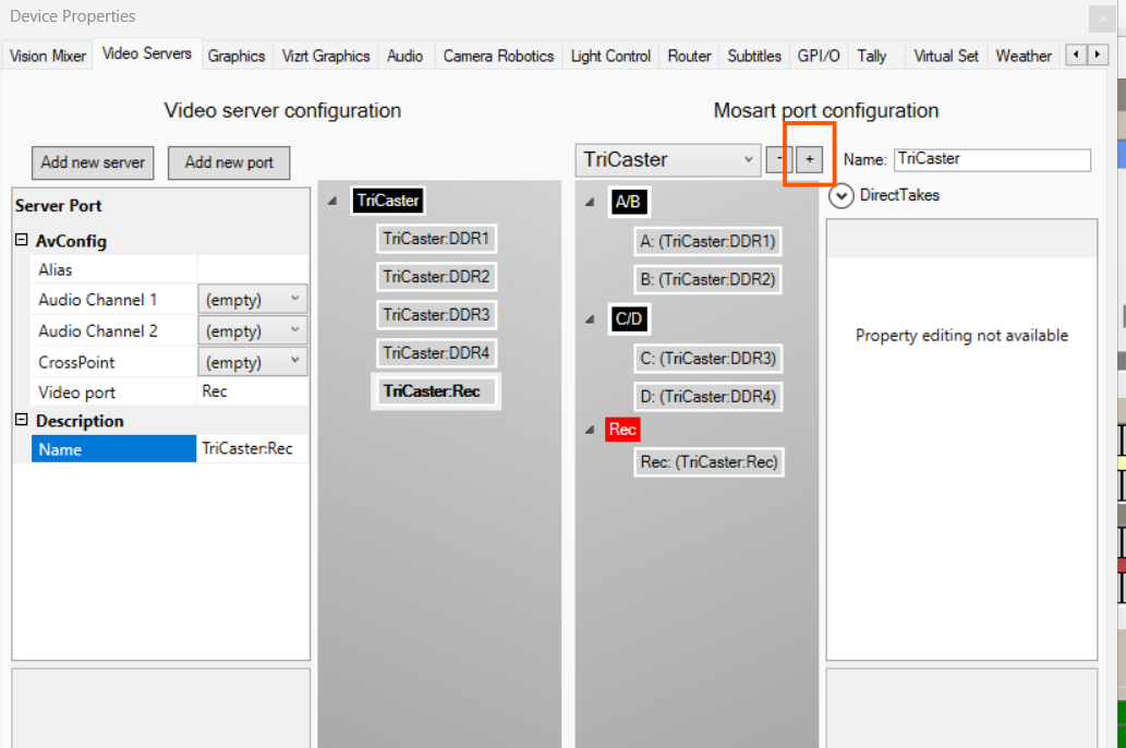
In Name, give this new virtual server an appropriate identity, for example, TriCaster.
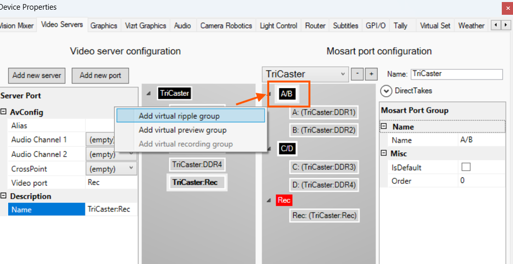
Right-click on the black box to add a virtual port group.
Click on the first Video server configuration (physical) port on the left half and drag-and-drop it to the first virtual one on the right under Mosart port configuration.
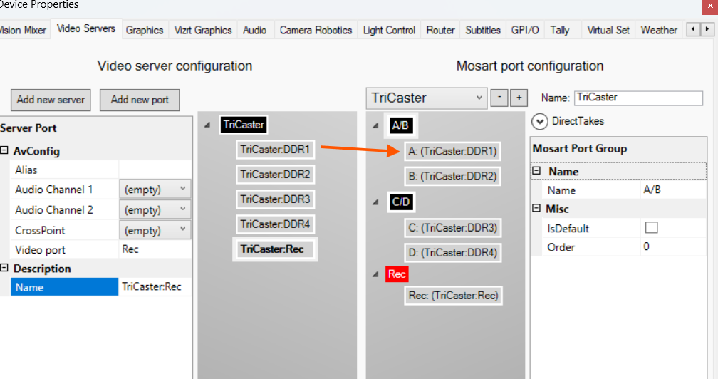
Repeat with the second port, by dragging another physical server port from the left side to pair them into an A/B ripple port playout group.
Add another virtual ripple group with 2 virtual ports and link them with the rest of the physical ports, if any.
A virtual recording group with one virtual port and link the physical recorder port to the virtual one in the same way as explained in step 12.
Click Apply, then Save & Close.
Restart AV Automation if needed.
To find session name
Note: To find session name:
Navigate to the TriCaster DataLink menu:
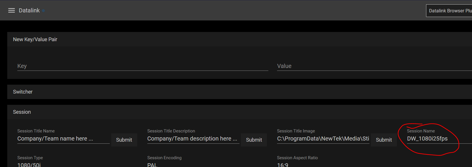
The session name is also displayed on the TriCaster home page (hidden menu at the top left corner):