
Viz Mosart Media Router Guide
Version 5.0 | Published October 18, 2021 ©
The Router Concept
Media Router does dynamic configuration changes to Viz Mosart servers by connecting Viz Mosart device representations with physical devices using a virtual 2D router matrix.
The following figure shows the 2D matrix. It is only possible to set crosspoints in the grey areas.
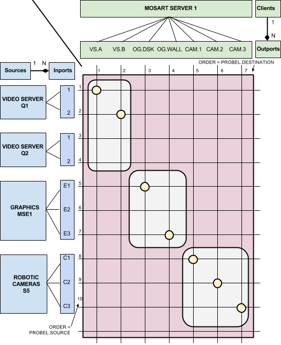
Physical devices are localised on the vertical dimension organized as Sources with Inports. A source may have one or several inports. Viz Mosart servers are localized at the horizontal dimension organized as Clients with Outports. A client may have one or several outports.
In the figure above we have the following configuration:
-
Sources:
-
Two video servers, Q1 and Q2 both with two video ports as inports.
-
One graphics system, MSE1 with three graphics engines as inports
-
One robotic camera system, S5 with three robotic cameras as inports
-
-
Clients: One single Viz Mosart Server (M1) with the following device representations as outports:
-
Two video ports, A and B
-
Overlay Graphics for DSK and WALL graphics
-
Three cameras to be controlled by robotic cameras, CAM1, CAM2 and CAM3.
-
By setting crosspoints the following Viz Mosart configuration is accomplished:
-
M1.VS.A = VS.Q1.1
-
M1.VS.B = VS.Q1.2
-
M1.OG.DSK = OG.MSE1.E1
-
M1.OG.WALL = OG.MSE1.E3
-
M1.RC.CAM1 = RC.S5.C1
-
M1.RC.CAM2 = RC.S5.C2
-
M1.RC.CAM3 = RC.S5.C3