The Viz Engine Render Pipeline supports GPU-accelerated particle systems.
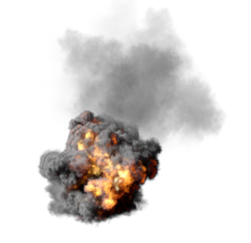
A particle system is used to simulate and render complex visual effects and natural phenomena (for example, fire, smoke, rain, snow, fog, dust, and explosions).
Note: The Classic Render Pipeline particle modifiers like Vortex or Turbulence are not supported.
This page contains information on the following topics:
Creating a Particle System
Drag a container to the scene tree (for instance a group).
Search for the Particle System plug-in and drag it over the container.
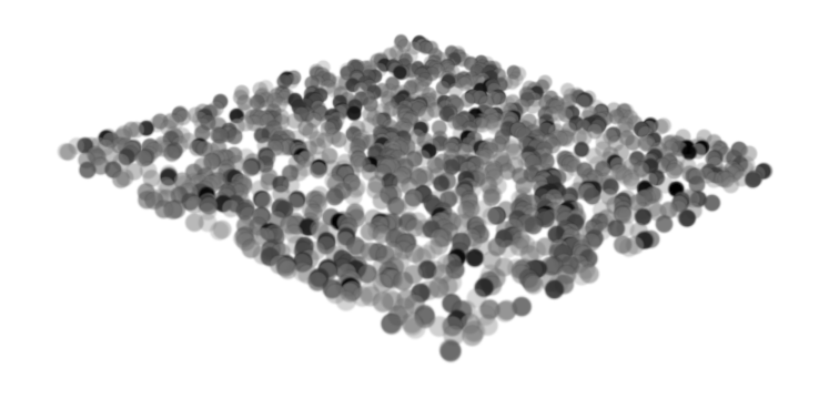
The Particle System plug-in starts emitting particles using the default values.
General Properties and Control
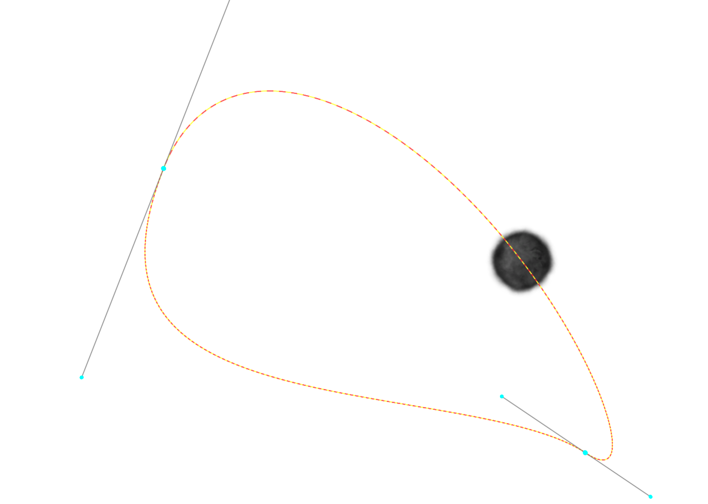
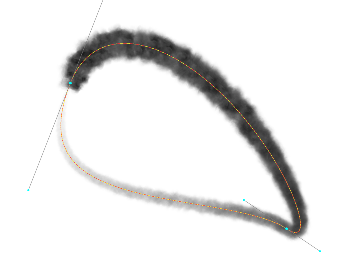
The reference defines if your particle system is part of your scene (World) or if it is running locally. Let's use an animated trail as an example:
Local | World |
|---|---|
The sorting of particles should always be turned on when alpha images are in use to guarantee a correct blending.
Common Parameters
Properties | Description |
|---|---|
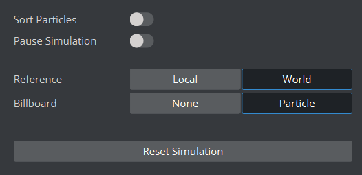
Sort Particles | Sorts the particles from back to front to produce correct alpha blending. |
Pause Simulation | Pauses/resumes the simulation. |
Reference | Changes the way the container transformation is applied to the particle system.
|
Billboard | Controls the rotation of each particle in relation to the camera.
|
Reset Simulation | Resets the particles and restarts the simulation. |
Properties
Emission
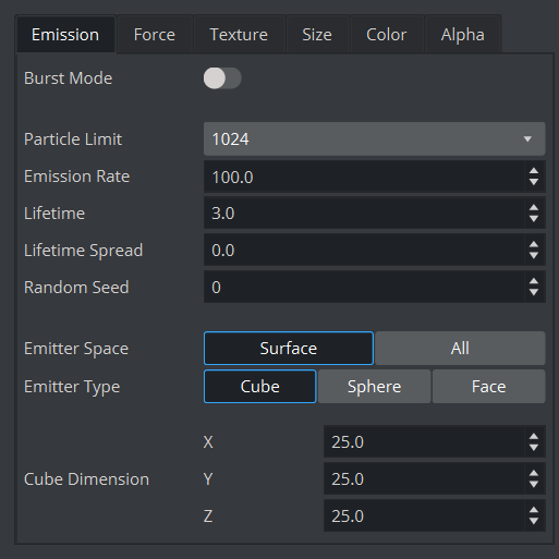
The way particles are created is based on their Emission Rate (how many particles are created per second) and their Lifetime (how long they are active, in seconds). This is only limited by the Particle Limit setting. For example, if you have an Emission Rate of 1000 particles and the Lifetime is three seconds, you'll need a minimum Particle Limit of 3000 to guarantee a constant emission of particles. If the combination of Emission Rate and Lifetime produces more particles than the limit set by this property, the excess particles won't be simulated/rendered.
In Burst Mode, the particle system generates as many particles as needed and then emits them at once each second.
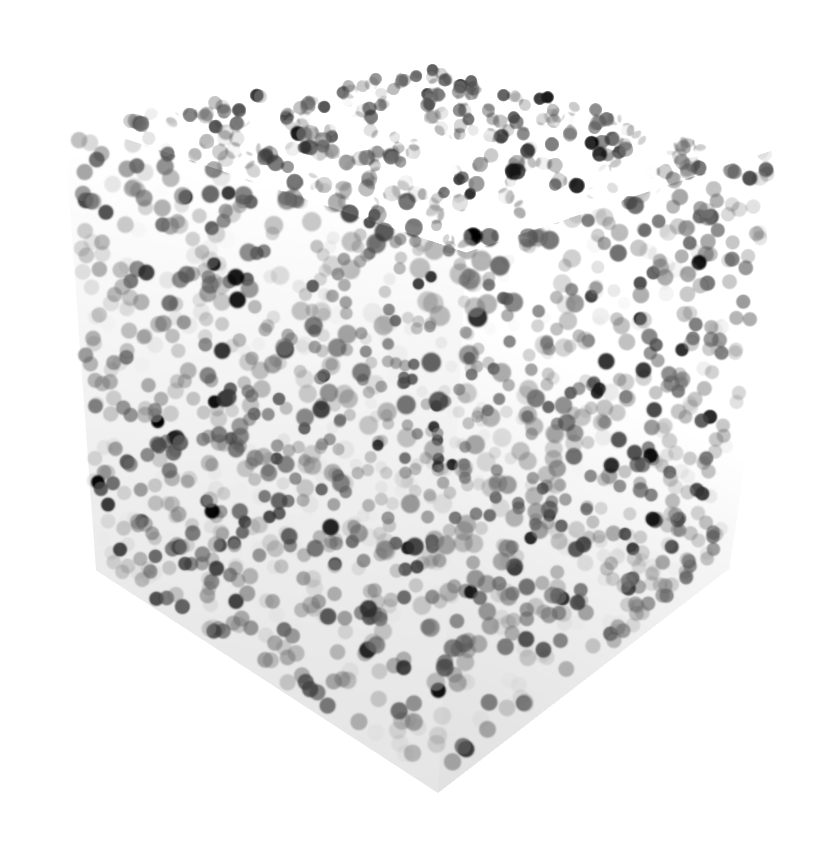
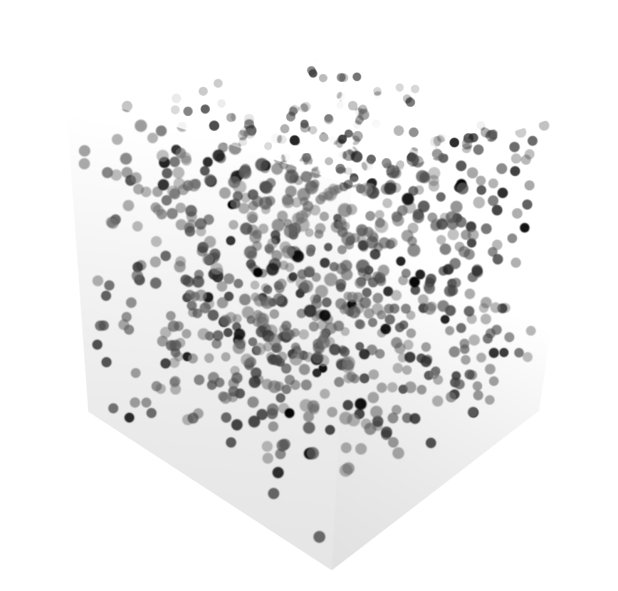
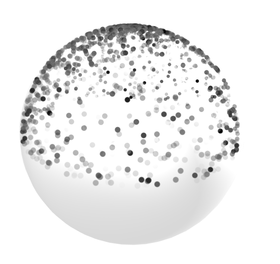
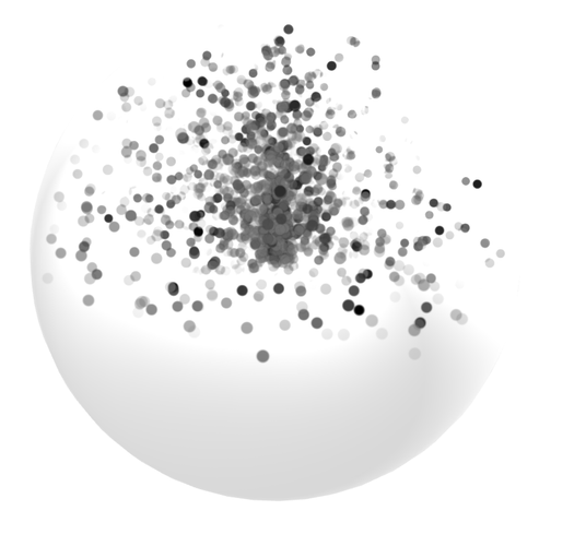
The location where particles are born and emitted is defined by the Emitter Type and the Emitter Space.
Type / Space | Surface only | All (whole volume) |
|---|---|---|
Cube | Particles are created within a cube, | Particles are created within a cube |
Sphere | Particles are generated inside a sphere (polar range 90), aligned to the faces | Particles are generated inside a sphere (polar range 90), aligned to the faces |
Face | Particles are generated based on a plane, the space is not relevant in this mode. | |
Emission Parameters
Properties | Description |
|---|---|
Burst Mode | Emits particles in the same instant (instead of being continuously emitted) when toggled on. |
Particle Limit | Limits the number of particles being simulated. |
Emission Rate | Controls the amount of particles emitted per second. Fractional values can be used. |
Lifetime | Determines the time (in seconds) for the particles to be simulated. |
Lifetime Spread | Controls the randomness for the life time of each particle. A random value between -Lifetime spread and Lifetime spread, is added to the life time of each particle. |
Random Seed | Sets the seed for the random number generator used by the random properties. |
Emitter Space | Controls from where in the emitter the particles are emitted.
|
Emitter Type | Selects the volume from which the particles are emitted. Dimensions for each type available can be changed using:
|
Force
How particles move is defined in the Forces tab. Depending on their emitter type, particles behave differently:
Particles born in a cube move in six different directions.
Sphere particles spread from a single point or sphere surface.
Particles on a plane travel in only one direction.
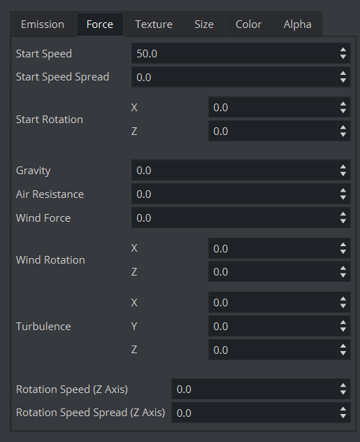
Start speed and the spread modifier (+ / -) defines the initial speed. This force is controlled by Gravity, Air Resistance and the Wind Force.
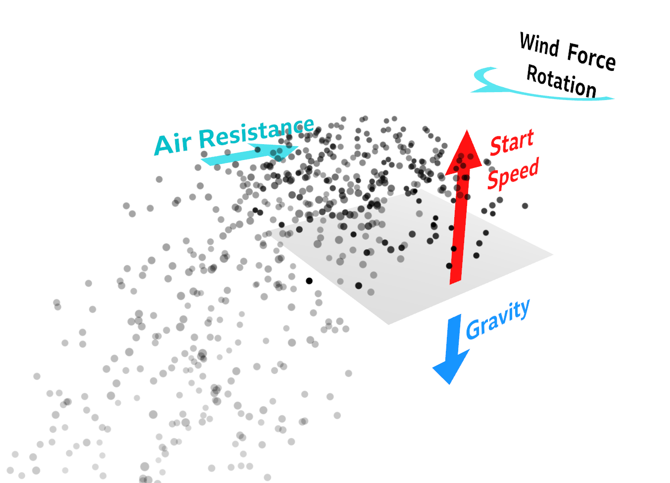
Example: Particles Emitted from a Face
With their initial starting speed, particles are emitted from the face pointing upwards.
Wind Force and the direction in x and z move the particles.
Air Resistance slows down the speed.
Gravity forces the particles to drop to the ground.
Force Parameters
Properties | Description |
|---|---|
Start Speed | Sets the initial speed for each particle. |
Start Speed Spread | Controls the randomness for the start speed of each particle. A random value between -Start speed spread and Start speed spread, is added to the start speed of each particle. |
Start Rotation X | Sets the initial speed rotation around the X axis. |
Start Rotation Z | Sets the initial speed rotation around the Z axis. |
Gravity | Controls the acceleration for the particles in the Y direction. |
Air Resistance | Sets the scale of a drag force proportional to the particle speed. |
Wind Force | Sets the magnitude of a force applied to each particle. |
Wind Rotation X, Wind Rotation Z | Determines the direction of the wind force on the X and Z axis. |
Turbulence X,Y,Z | Controls the scale of a random perturbation, of the speed of each particle on each axis. |
Rotation Speed (Z axis) | Sets particle angular velocity around the Z axis. |
Rotation Speed Spread (Z axis) | Controls the randomness for the particle rotation speed (Z axis) of each particle. A random value between -Particle rotation speed spread (Z axis) and Particle rotation speed spread (Z axis), is added to the particle rotation speed (Z axis). |
Texture
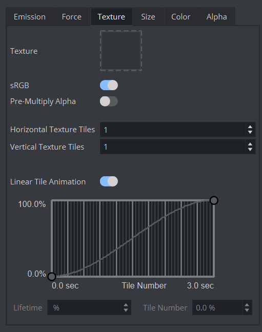
Particles require a texture to look good. These textures can be static RGBA images or tile sequences. (for example, explosions or smoke). Sequences should be in RGBA format and tiled. The sample below shows a 5x5 tile explosion animation. The number of particles on such an animation can be kept quite low (for example, about 20 particles), just a bit of turbulence and x rotation is needed.
Texture Parameters
Properties | Description |
|---|---|
Texture | Selects a texture to apply to each particle. |
sRGB | Treats the texture as an sRGB encoded texture (checked by default) when checked. |
Pre-Multiply Alpha | Multiplies the final color of the rendered particles with the alpha from the texture. |
Horizontal Texture Tiles | Sets the number of horizontal tiles in the texture. Used to control the sprite sheet animation. |
Vertical Texture Tiles | Sets the number of vertical tiles in the texture. Used to control the sprite sheet animation. |
Linear Tile Animation | Calculates the texture tile selected for rendering by linearly interpolating within the horizontal and vertical tiles using the current life time of the particle when checked. Uncheck to control the tile selection using an animation curve. |
Tile Number | Controls the tile number during its lifetime. Horizontal axis is the lifetime in seconds, vertical axis controls the tile number based on the percentage of total tiles. |
Size
Size Parameters
Properties | Description |
|---|---|
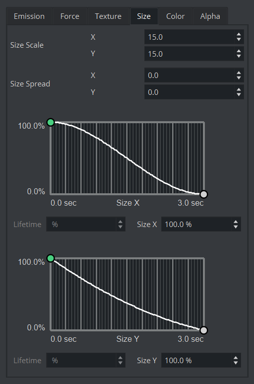
Size Scale X,Y | Scales for the size of the particle, where a particle is represented by a rectangle. |
Size Spread X,Y | Controls the randomness for the size scale of each particle. A random value between -Size Spread X,Y and Size Spread X,Y is added to the size scale. |
Size X, Y | Controls the particle size during its lifetime. Horizontal axis is the lifetime in seconds, vertical axis controls the particle size based on a percentage of the size scale. |
Color
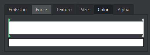
Use the color ramp box to control the particle color during its lifetime. The leftmost part of the ramp is the initial color and the rightmost is the final color. Multiple color handles can be created and moved. Change the color of each color handle in the smaller box below the color ramp.
Alpha
Alpha Parameters
Properties | Description |
|---|---|
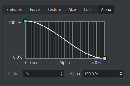
Alpha | Controls the particle alpha during its lifetime. Horizontal axis is the lifetime in seconds, vertical axis controls the alpha value |

