
Viz Engine
Version 3.10 | Published April 03, 2018 ©
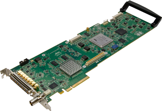
Matrox X.mio, X.mio2 and X.mio2 Plus
This section contains information on the following topics:
X.mio2 and X.mio2 Plus Cables and Connectors
The connectors for X.mio2 and X.mio2 Plus are:
-
PCIe board compliant to PCIe 2.0 in x8 or x16 slot
-
x2 or x4 SDI video inputs in SD and HD
-
x4 SDI video outputs in SD and HD
-
x16 In / x32 Out, unbalanced AES/EBU audio
Because of the large number of I/O connections, the X.mio2 and X.mio2 Plus boards are equipped with Sub-D connectors. A breakout-cable or rack mountable Break Out Box (BOB), which translates the Sub-D connectors to regular connectors/plugs, is included for every machine.
The connectors for X.mio are:
-
133 MHz PCI-X board compliant to PCI-X standards 1.0b and 2.0
-
x2 SDI video inputs in SD and HD
-
x4 SDI video outputs in SD and HD
-
x8 In / x16 Out, balanced XLR AES/EBU audio
-
x16 Embedded Audio I/O Channels per SDI Stream
X.mio2 Standard Cable Configuration
This section contains the standard configuration, set in the in the Viz Configuration, to cable a Viz Engine to the correct SDI IN and OUT connectors.
Viz Engine Single Channel Configuration
-
SDI OUT A: mapped to Program Fill
-
SDI OUT C/KEY: mapped to Program Key
-
SDI OUT B: mapped to Preview Fill
-
SDI OUT D/KEY: mapped to Preview Key
-
SDI IN A: mapped to Video1
-
SDI IN B/KEY: mapped to Video2, and so on
Dual Channel Configuration
A Viz Engine configured as Dual Channel utilizes two graphics cards and runs two instances of the Engine on a single computer. When running a Dual Channel setup, video inputs are hardware resources on the Matrox board that can not be shared. If one input for both Viz Engine channels is required, split the signal and apply it to the two video input connectors. Each Matrox video input can only be mapped in one Viz Engine instance and has to be set to unused in the other instance.
-
Channel 1:
-
SDI OUT A: mapped to Program Fill
-
SDI OUT C/KEY: mapped to Program Key
-
SDI IN A: mapped to Video1 for the first channel
-
SDI IN B/KEY: unused for the first channel, and so on.
-
-
Channel 2:
-
SDI OUT B: mapped to Program Fill
-
SDI OUT D/KEY: mapped to Program Key
-
SDI IN A: unused for the second channel
-
SDI IN B/KEY: mapped to Video1 for the second channel, and so on
IMPORTANT! Both Viz Engines must be set to the same genlock setting.
-
Trio Box CG/Viz Trio OneBox Configuration
-
Program:
-
SDI Out A: mapped to Fill
-
SDI OUT C/KEY: mapped to Key
-
SDI IN A: mapped to Video1
-
SDI IN B/KEY: mapped to Video2, and so on.
-
-
Preview:
-
SDI Out B: mapped to Fill
-
SDI OUT D/KEY: mapped to Key
-
no Inputs are mapped by default
-
Breakout Cables and Connectors
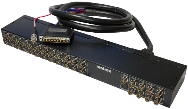
A Breakout Box (BOB) is often used for Viz Engine solutions that need to be rewired in regular intervals. The 1U Rack unit chassis is designed to fit into a standard 19” rack.
This section contains information on the following topics:
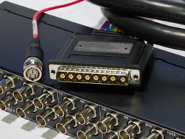
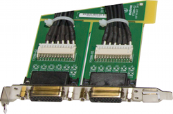
Video Cables for X.mio Series
This image shows the cables responsible for transmitting any video related signals to and from the X.mio2 Plus board.
Video Connectors for X.mio2 Plus
The front panel of the X.mio2 Plus breakout box provides the user with 8 or 9 standard BNC connectors.
-
x2 or x4 HD/SD SDI In
-
x4 HD/SD SDI Out
-
x1 Analogue Ref In
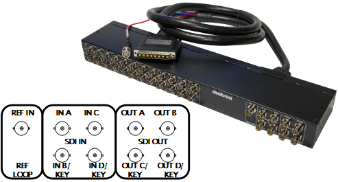
Video Connectors for X.mio2
The front panel of the X.mio2/2 Plus breakout box provides the user with 8 or 10 standard BNC connectors.
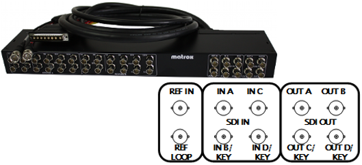
-
x2 or x4 HD/SD SDI In
-
x4 HD/SD SDI Out
-
x1 Analogue REF IN
-
x1 Analogue REF LOOP
IMPORTANT! When using the REF IN connector on the Matrox X.mio2 board for synchronization, the REF LOOP connector must be terminated with a 75 Ohm resistor unless it is being used to loop an incoming Genlock signal.
Video Connectors for X.mio
The front panel of the X.mio breakout box provides the user with 8 standard BNC connectors.
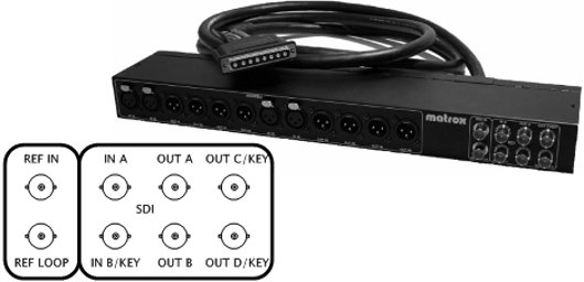
-
x2 HD/SD SDI In
-
x4 HD/SD SDI Out
-
x1 Analogue REF IN
-
x1 Analogue REF LOOP
IMPORTANT! When using the Ref. In connector on the Matrox X.mio board for synchronization, the Ref. Out Loop connector must be terminated with a 75 Ohm resistor unless it is being used to loop an incoming Genlock signal.
Audio Connectors for X.mio2 and 2 Plus
On the X.mio2/2 Plus breakout box, each of the two audio bays, A and B, consists of four female BNC audio input channels and of eight female BNC audio output channels.
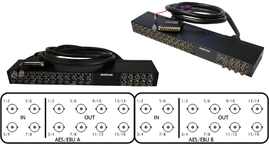
Note: Bay cables are not included.
On the backside of each breakout box there are two connectors labeled AUDIO-A and AUDIO-B. The included cables are used to connect the corresponding plugs of the X.mio series to the computer.
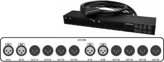
Audio Connectors for X.mio
The front side of the X.mio breakout box hosts various audio in- and outputs. Each of the two audio bays, A and B, consists of two female AES/EBU audio input channels and of four male AES/EBU audio output channels.
Video Cable Assignment
Connect the relevant video input(s) and output(s), and the reference signal(s) as per the labels attached to each cable.
A reference signal can be attached to the reference input connector ANALOG REF IN, which can be fed with any analogue Genlock signal, such as a black burst or Tri-level as required.
If the reference signal used for synchronization is relayed from a Matrox X.mio and X.mio2 to a graphics card, make sure to check that all internal connections between the graphics card and its SDI extension are connected correctly, and that the extension is correctly supplied with power.
When the ANALOG REF IN connector is used with a Matrox X.mio or X.mio2 board for synchronization, the ANALOG REF LOOP OUT connector must be terminated with a 75 Ohm resistor unless it is being used to loop an incoming Genlock signal. The ANALOG REF LOOP OUT for the X.mio2 Plus is terminated by default, and so only supports REF IN on the actual board.
Audio-extension Card
The audio-extension card and audio cables are part of the X.mio series break-out box or the X.mio series cable kit (that comes with the X.mio series boards), and needs to be installed when AES/EBU audio support is required. The card is an extension for the connectors, and does not provide any extra functionality. For installations that require embedded audio, or no audio at all, this extension is not required.
IMPORTANT! The Matrox audio-extension card only supports digital audio.
By default, the audio-extension card will consume one additional free slot on the motherboard. The card is supplied with the Matrox X.mio series boards in terms of power and data.
In some cases, the design of the audio-extension card makes it hard to mount it at a location with an underlying PCIe slot. Therefore, it is an option to remove the back-end from the Audio-extension Card instead of using another PCI or PCI-X slot. However, it is in most cases possible to mount the extension card in any slot in the machine, unrelated to the underlying slot’s design, without removing its back-end.
Removing the back-end of the extension card will free any connection to the motherboard. As a result, it may react more sensitively to transportation and tension introduced by the external audio cables connected to it. Therefore, the above-mentioned procedure should only be applied to machines residing in stable environments like a dedicated machine room. Do not apply these instructions to machines intended to be used for outside broadcasting or equipment that will be moved around a lot.
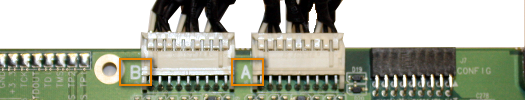
To Connect the Audio-extension Card to the Video Board
IMPORTANT! The Matrox audio-extension card only supports digital audio.
-
Locate the connectors on the audio-extension card labeled A and B.
-
Locate the connectors on the video board labeled A and B.
-
Use the cables to connect A on the audio-extension card to A on the video board, and do the same for the B connectors.
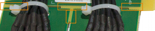
To Remove the Audio-extension Card Back-end
-
Locate the audio-extension card’s weak spots
-
Carefully break the connections.
Caution: Do not break the weak spots that hold the two remaining pieces together.
X.mio2 License Upgrade
The Matrox X.mio2 and X.mio2 Plus boards include all SD codecs except D10 Television/D12 Television. These two boards can be upgraded to any higher class by a license upgrade. To do this, use the Matrox X.info utility.
To upgrade a video board to a higher class, it is necessary to generate a Matrox Dongle Information File (.MDIF), and then upgrade with a Matrox Dongle Upgrade File (.MDUF). It is also possible to reset to factory settings at any time.
The X.mio2 Plus board video inputs can also be upgraded from 2 to 4.
Note: Driver versions older than 4.0.0-126 do not support the upgrade and revert features.
To Generate a Matrox Dongle Information File (.MDIF)
-
Open the Matrox X.info utility on the Windows taskbar.
-
Select Hardware, and click the Upgrade Model button on the right.
-
From the appearing menu, choose Generate Matrox Dongle Information File (.MDIF).
-
Select to save the file to a specified location.
-
Once the file is created a confirmation dialog box will appear.
-
Click OK to dismiss the confirmation dialog box.
-
Locate the file and send it to your local Vizrt representative (to find the local Vizrt customer support team, please visit www.vizrt.com).
-
Once the request to purchase an upgrade has been sent, an MDUF file will be sent in return from Vizrt.
-
To Upgrade with a Matrox Dongle Upgrade File (.MDUF)
-
Open the Matrox X.info utility on the Windows taskbar.
-
Select Hardware, and click the Upgrade Model button on the right.
-
From the appearing menu, choose Upgrade Board from Matrox Dongle Upgrade File (.MDUF).
-
Click Browse to locate and select the .MDUF file to start the upgrade process.
-
Restart the machine for the changes to take effect.
To Reset to Factory Settings
-
Open the Matrox X.info utility on the Windows taskbar.
-
Select Hardware, and click the Upgrade Model button on the right.
-
From the appearing menu, choose Reset to Factory Settings.
-
Restart the machine for the changes to take effect.