Device Calibration
For Viz Mosart to operate frame accurately, the system must be calibrated so that Viz Mosart knows the latency of each piece of gallery equipment it controls. This section describes the calibration tests that reveal those latencies, and where to enter the measured values.
Introduction
For correct frame accurate performance, Viz Mosart depends on several things:
A proper genlock setup (described below).
Gear supporting frame accurate performance.
A proper calibration session during setup.
Viz Mosart currently supports frame accurate and deterministic control of the switcher, the audio mixer, and the video server, provided the gear involved supports this. Frame accurate control will be expanded to more devices in future updates.
About deterministic behavior and latency
For frame accurate control to work, the gear being controlled must support it. This comes down to two main traits.
First, the gear must have a genlock mode, accept a genlock feed, and respond to incoming commands aligned to the start of one of the following frames. One exception is audio gear, which often does not support genlock. Audio gear should still respond predictably to incoming commands.
Second, gear may have some latency (delay) in its response to vital incoming commands such as cross point switching, audio fader changes, and clip start. That delay must always be the same, because only then can Viz Mosart compensate for it.
For example, a video server may take 7 frames to respond to a clip play command, but it must always take 7 frames for that command.
What frame accurate control means
Frame accurate control means two things:
You get deterministic (repeatable) behavior from the gear being controlled.
Viz Mosart compensates for any latency (delay) involved when controlling that gear.
To make this happen, all the gear involved must be connected to the same genlock network, and the Viz Mosart server must run from the same timing reference. Viz Mosart must also learn how the controlled gear behaves in terms of latencies.
For example, to start a clip frame accurately, Viz Mosart must know two things:
Exactly how many frames it takes the video server to respond to a Play command.
Exactly how many frames it takes the switcher to respond to a cross point command.
The calibration process finds these delay values and configures Viz Mosart accordingly. The following sections present the calibration process as a series of tests.
What frame accurate control does not mean
Frame accurate control does not mean that everything suddenly happens in an instant, without any delays. Viz Mosart cannot speed up the gear it controls.
Frame accurate control does not mean that Viz Mosart can squeeze predictable, deterministic behavior out of unpredictable gear.
Frame accurate control does not mean that Viz Mosart can produce reliable results controlling gear that has not been properly set up with genlock and timecode.
Frame accurate control does not mean that Viz Mosart can produce reliable results out of a machine room that has not been properly set up and calibrated.
General setup
To get frame accurate behavior, both Viz Mosart and the gear it controls require several setup steps, described here.
Note: Most of these steps are obvious and have probably already been applied. They are mentioned for completeness.
Genlock
The studio equipment has to behave as frame accurate gear in its own right, so at least the following must be connected to the same genlock network:
The video switcher, for frame accurate cross point switching.
The video server, for frame accurate file playback.
The video recorder, if any, for frame accurate recording.
Other gear in the setup may also need genlock, but these are the main players. The format in which genlock is delivered does not matter (analog blackburst or SDI), and mixing these formats is fine, provided the overall timing is tight between the connected devices.
The Viz Mosart server needs a reference of its own, and where that reference comes from depends on the clock source you run. With a Plura timecode card, the server takes a genlock feed into the card, so it joins the same genlock network as the gear listed above. From Viz Mosart 5.15.0 you can run PTP instead. Windows then disciplines the system clock to a PTP grandmaster over the network, and the server needs no genlock feed and no card.
PTP changes only how the Viz Mosart server itself gets its reference. The video switcher, the video server and the video recorder still need genlock on both routes. See PTP Setup.
Timecode
In addition to genlock, the video recorder, if any, must be connected to the timecode house clock network. Different timecode formats can be mixed, provided the connected devices receive the same timecode for the same frame.
Whether the Viz Mosart server needs that same house timecode depends on the clock source. On the Plura route it does, and the Plura card delivers the timecode to the server. Under PTP it does not, because Windows disciplines the system clock to the PTP grandmaster instead.
Viz Mosart Server
A Plura timecode card (such as the PCIe 3G) connects the Viz Mosart server to both the genlock and the timecode network. The same Plura card delivers timecode to the Viz Mosart server, and both digital VITC and ATC-VITC are supported.
From Viz Mosart 5.15.0, the clock source can be PTP instead. Windows disciplines the system clock to a PTP grandmaster, so no card has to be installed in the server computer. See PTP Setup.
Viz Mosart Genlock Settings
In AV Automation, go to Devices > Properties > Genlock and set Viz Mosart in Genlock mode. Then set the clock source to match the route you run, either the Plura card or PTP.
Enter the latencies measured by the tests described here on the AV Automation Genlock tab, in the Calibration box.
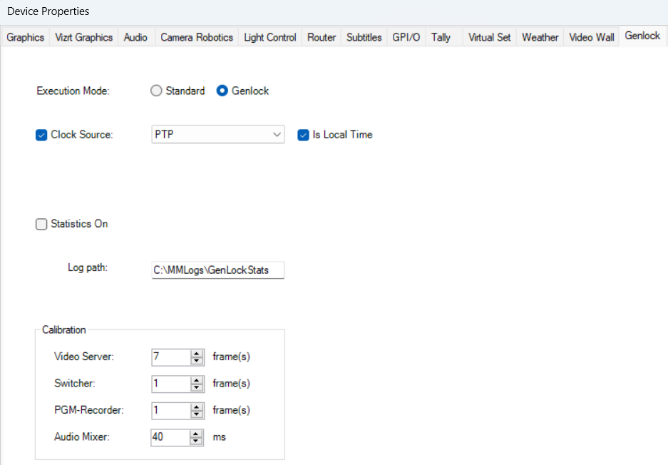
The four fields in the Calibration box are:
Field | Measured by | Unit |
|---|---|---|
Video server command latency | Frames | |
Switcher command latency | Test A3 | Frames |
PGM-Recorder latency | Test A4 | Frames |
Audio mixer command latency | Test A6 | Milliseconds |
Video Recorder Settings
For Story Recorder users only, set the video recorder to an I-frame only format for the intermediate recordings. This works around some issues with long-GOP format recordings. It has no impact at all on the final, consolidated show clips.
Video Server Settings
All the video server ports used for clip playout through Viz Mosart must have identical play command latency values. That is, these ports must behave in identical ways. One of the calibration tests described below focuses on this.
Info: Viz Mosart cannot perform frame accurately with ports that have different latency values.
Audio and video sync
The audio-video lip sync on the final PGM output is expected to be perfectly set up. One of the calibration tests below involves audio mixer latency measurements, and that test only makes sense if the system is correctly set up to begin with.
Calibration Overview
The table below lists the available calibration tests. There are two series: the recommended A-series, and the alternative B-series tests that can be considered where available.
When setting up frame accurate mode for the first time, perform all tests in order, choosing the A or B series where available.
Once set up, the calibration tests only need to be performed again after changes in the machine room setup, or firmware updates of the gear being controlled.
Test | Alternative | Needs first | Gear | Latency value | Optional | Default | Description |
|---|---|---|---|---|---|---|---|
- | Timecode burn-in feed, recorder, Clip Tool | Recorder in-out latency | Optional | 0 frames | Any latency added by the video recorder. | ||
A1 (if you ran it) | Recorder, Clip Tool, re-cabling | Video server command latency | 1 frame | The time it takes the video server to respond to a play command and start playing. | |||
A2 (not B2) | Mobile phone or recorder | Switcher command latency | 1 frame | The time it takes the video switcher to respond to a cross point switch command. | |||
A3 | Two camera feeds, Story Recorder, Clip Tool | PGM-Recorder latency | 0 frames | The sum of in-out latencies introduced by the video switcher, any downstream gear in the PGM output path, and the video recorder. Relevant for Story Recorder only. | |||
- | Recorder, NLE | Audio and video lip sync | Optional | - | Test of audio-video lip sync offset as set up in the server room. | ||
A2 and A3 | Recorder or Story Recorder, Clip Tool or NLE | Audio mixer command latency | 0 ms | The time it takes the audio mixer to respond to a fader command. | |||
- (assumes switcher = 1 frame) | Mobile phone | Video server command latency | 0 frames |
Before you Start
Gear for the whole session
A video recorder able to record a single port and the PGM output.
Harmonic Clip Tool, or an equivalent that shows per-frame timecode.
A professional NLE (Premiere Pro, Final Cut Pro) for the two audio tests.
A mobile phone that can film a monitor, if you run A3 or B2.
Two camera feeds with visibly different pictures, for A4.
Cables to patch a playout port directly into the recorder input, for A2.
The test clips, at your own frame rate. See Test clips.
The rule every test follows
Set the latency you are about to measure to 0, and make sure the latencies you already measured are entered on the Genlock tab. Test B2 is the one exception: it starts at 20 frames and you subtract what you find.
What feeds the Calibration box
A1 and A5 produce no setting of their own. A1 gives you a number you subtract inside A2. A5 is a sanity check on the machine room before Viz Mosart is involved at all.
Test Clips
The calibration clips are built for these tests and are supplied with the calibration package. They must match the frame rate and raster of the house standard, so a facility running anything other than 25 fps needs its own set. Build them to the specification below.
Clip | Video | Audio | Used by |
|---|---|---|---|
| Frame 0 is a single white frame carrying a large blue 0. Every following frame is black with its frame number burned in, counting 1, 2, 3 and up. | A clapper transient at full level starting exactly on frame 0. | A2, A3, A5, B2 |
| Solid yellow with burned-in timecode. | Silent. | A3, A6, B2 |
| Solid pink with burned-in timecode. | Sine tone at full level from the first frame, with no fade-in. | A6 |
Rules for a home-made set:
Same frame rate and raster as the house standard.
I-frame only, about 10 seconds long.
The white frame in
WhiteBlack-Clapper-Numis exactly one frame.No audio fade at the head of
Pink-Sine-TC. A6 measures audio onset against the first pink frame, so an encoder-added ramp silently corrupts the result.
Rundown Recipes
These are the breakdowns of the test rundowns mentioned in the calibration tests. Test rundowns are not easy to make available, so create your own set as described below.
Info: Use the indicated clips. They were specifically designed for the calibration process.
Rundown Calibration-A2
Camera
Clip
WhiteBlack-Clapper-Numplayout port A.
Rundown Calibration-A3
Camera
Clip
Yellow-Silent-TC, auto-take 5s, A/B roll.Clip
WhiteBlack-Clapper-Num, A/B roll.
Rundown Calibration-A4
Camera 1
Camera 2, with a visually different feed than Camera 1.
Rundown Calibration-A5
Camera
Clip
WhiteBlack-Clapper-Num, A/B roll.Camera.
Rundown Calibration-A6
Camera
Clip
Yellow-Silent-TC, A/B roll, fader with audio ripple, crossfade in/out set to 0, autotake 5s.Clip
Pink-Sine-TC, A/B roll, fader with audio ripple, crossfade in/out set to 0.
Rundown Calibration-B2
Camera
Clip
Yellow-Silent-TC, A/B roll.Clip
WhiteBlack-Clapper-Num, A/B roll.
A-series Calibration Tests: The Recommended Set
Calibration A1: Recorder in-out Latency (optional)
This test is optional, but still recommended if you have the required gear available.
The video recorder is required in several calibration tests, and in some of these it is important to know whether the video recorder introduces any in-out (throughput) latency. For example, if the recorder is recording a clapper board hit at a given timecode, will it show up in the recording at the same timecode, or a few frames later?
A professional video recorder normally has zero in-out latency, and your recorder will likely behave the same. If in doubt, perform the test.
What is the plan?
Connect a feed with burned-in, actual house clock timecode directly to the recorder input and make a short recording. No Viz Mosart is involved here. Then check the recording and compare the difference between the burned-in timecode and the recorder's own timecode track. The difference is the recorder latency.
Setup
This test is somewhat demanding in terms of gear. You need a feed showing the live house clock timecode burned in. This can be achieved in several ways:
A zero-latency camera pointed at a zero-latency timecode display.
A zero-latency camera with built-in timecode display.
A device such as a Rubidium, emitting an SDI feed with zero-latency burn-in timecode.
Some re-cabling is also needed for this test.
Test material and gear
Timecode feed as described above.
The video recorder being tested, properly set up with genlock and timecode.
A tool to inspect the recorded video, such as Harmonic's Clip Tool.
Test
Connect the timecode feed directly to the recorder input.
Make a recording a few seconds long.
Inspect the recording using Clip Tool (or similar).
Establish the difference in frames between the burn-in timecode shown in the video area and the timecode associated with the frame (from the recorder's timecode track). In the figure below, the latency found is 2 frames.
Remember this latency as the recorder in-out latency. It is needed later.
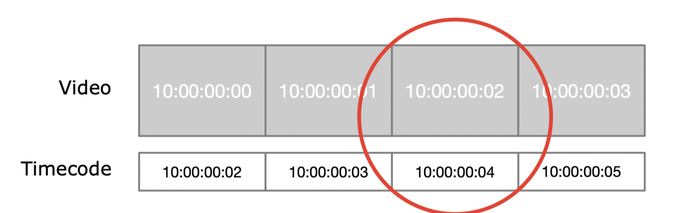
In the example above, the 10:00:00:02 timecode from the feed being recorded is matched with a 10:00:00:04 timecode from the video recorder's own timecode track. The recorder in-out latency here is 2 frames.
Calibration A2: Video Server Command Latency
This test measures the video server command latency, which is the time it takes the video server to respond to a play command, expressed in frames. Perform the test for each of the individual video server ports involved in the playout of rundown clips.
What is the plan?
Cue a clip in the video server that starts with a single white frame, followed by black frames. At a known timecode, Viz Mosart instructs the video server to play the clip while the playback port is being recorded. Check the recording and look for the recorder timecode associated with the last white frame, which is the first frame being played. The difference in timecodes is the latency.
Setup
This setup needs some re-cabling. To measure the latency of playout port A, for example, use a cable to connect port A directly to the recorder input. Re-cable to test the other ports.
Test material and gear
Rundown:
Calibration-A2. See Rundown recipes above.A video recorder. If you do not have a recorder, run alternative test B2 instead.
A tool to inspect the recorded video, such as Harmonic's Clip Tool.
Test
Cable the port being tested directly to the recorder input.
On the AV Automation Genlock tab, set video server command latency to 0.
Load rundown
Calibration-A2.Start the recording.
Start the rundown and run story by story.
A few seconds into the clip, stop the recording.
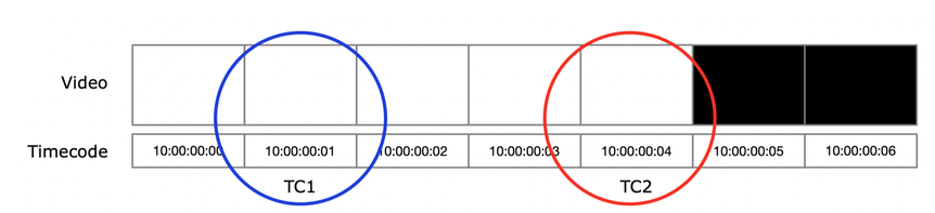
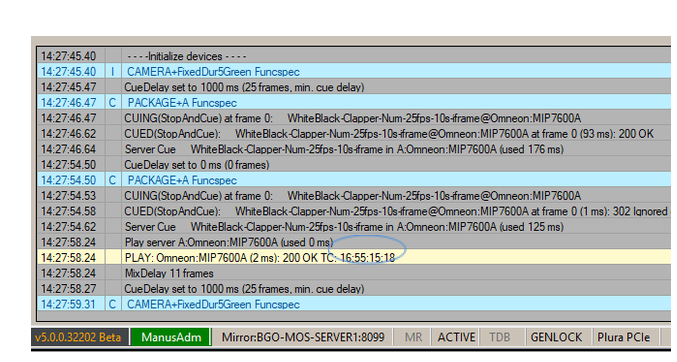
In the AV Automation Log area (see Figure 3 below), look up the timecode for the moment the video was started. Call this TC1 (the blue circle in Figure 2 below).
In the recording, using Clip Tool or similar, look up the timecode of the last white frame. This is TC2 (the red circle).
The command latency for this port is the difference in frames between TC1 and TC2. In the figure below, that is 3 frames of latency.
If you measured the recorder in-out latency, subtract that value from the latency found in the previous step.
On the AV Automation Genlock tab, set video server command latency to the latency found.
Repeat this test several times for the same port, to check for consistent behavior. Then repeat the test for each of the playout ports.
Info: All playout ports must have identical latency values.
Calibration A3: Switcher Command Latency
This test only makes sense, and only produces a reliable result, if you were able to run the recommended test A2 beforehand rather than the less preferred test B2. If you had to use test B2, which assumes a switcher command latency of 1 frame, skip test A3 and keep the 1 frame value.
This test measures the switcher command latency: the time it takes the switcher to respond to a cross point command, expressed in frames.
What is the plan?
While a yellow clip is playing, cue and start a second clip with burned-in increasing frame numbers (0, 1, 2 and so on) that starts playing with frame #0 exactly at the take point. Video server latency was measured in the previous test. At the same time, open the cross point for the clip and record the PGM output. If frame #2 shows as the first frame of the clip instead of the expected #0, the switcher has a 2-frame command latency.
Test material and gear
Rundown:
Calibration-A3. See Rundown recipes above.A mobile phone or video recorder for recording the PGM output, for example using AV Automation or Harmonic's Clip Tool to start the recording on the video server.
Test
Make sure cabling is restored to normal.
On the AV Automation Genlock tab, set switcher command latency to 0.
On the AV Automation Genlock tab, make sure that video server command latency is calibrated and specified.
Load rundown
Calibration-A3.With a mobile phone or recorder, record a video of a monitor showing the PGM output.
Start the rundown.
Stop the recording once the rundown is completed.
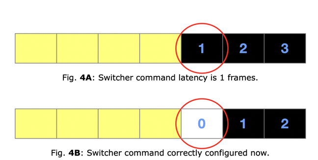
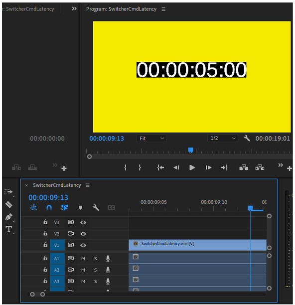
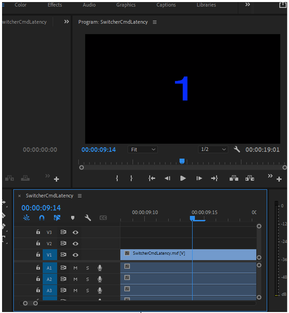
In the recorded video, locate the first non-yellow frame. The big blue number shown is the latency. See Figure 4 below as an example.
On the AV Automation Genlock tab, set the switcher command latency value to the number found.
To confirm, repeat the test from step 4.
The first non-yellow frame should now be a white frame with a big blue 0, as shown in Figure 4B below. Success.
Repeat this test at least 5 times. All tests should result in the same latency value.
 |  |
Calibration A4: PGM-recorder Latency
Info: This test is relevant for Story Recorder users only.
This test measures PGM-recorder latency, which is the sum of in-out latencies from the vision mixer, any additional gear in the PGM output path, and the in-out latency of the video recorder used for Story Recorder.
What is the plan?
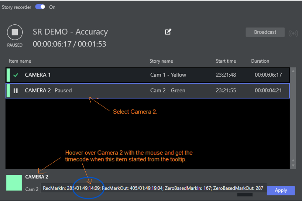
In Story Recorder, take Cam1 followed by Cam2 while recording the PGM output. Use the Story Recorder panel to get the house clock timecode for when Cam2 was taken. Then check the recording, locate the cut to Cam2, and find the recorder timecode for that moment. The difference between the two timecodes is the PGM-recorder latency.
Test material and gear
Rundown:
Calibration-A4. See Rundown recipes above.Two camera feeds.
Story Recorder's video recording feature.
A tool to inspect the recorded video, such as Harmonic's Clip Tool.
Test
On the AV Automation Genlock tab, make sure the switcher command latency value is calibrated and specified.
Load rundown
Calibration-A4.Enable Story Recorder. Wait for it to enter Record mode.
Start the rundown.
Once the rundown has ended, pause Story Recorder.
In the Story Recorder panel on screen (see Figure 7 below), locate the timecode of the take of Camera 2. Call this TC1 (the blue circle).
Using Clip Tool or similar, load the recorded clip and locate the hard cut from cam1 to cam2.
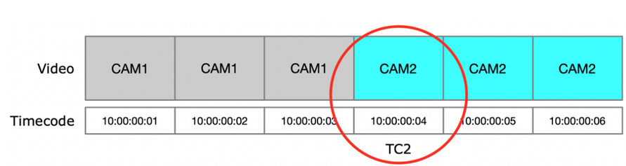
Note the recorder timecode of the first frame of the Camera 2 take. Call this TC2 (the red circle).
On the AV Automation Genlock tab, set PGM-recorder latency to the number of frames between TC1 and TC2.
Calibration A5: Audio and video lip sync (optional)
Info: This test is optional and is defined here for completeness, as this has probably already been taken care of in your setup.
This test checks the lip sync relation between video and audio as found on the PGM output. The goal is to have audio and video perfectly in sync, even before Viz Mosart comes into play.
What is the plan?
Play a clapper-board style clip into an open cross point with open audio faders, record the PGM output in a video recorder, and check the result. This does not test Viz Mosart, only the PGM signal.
Test material and gear
Rundown:
Calibration-A5. See Rundown recipes above.A video recorder for recording PGM.
A professional NLE such as Premiere Pro or Final Cut Pro.
Test
Load rundown
Calibration-A5and Set as Next the clapper clip, if this is not the first story in the rundown. This cues the clapper clip on PGM.Observe which port is cued on PGM.
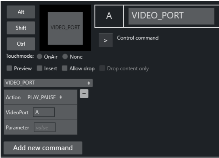
Prepare a keyboard shortcut (see Figure 10 below) instructing the video server to play the clip on the port cued on PGM.
Open the audio fader for the same port in the AV Automation UI.
Start the recorder.
Press the keyboard shortcut to start the clip.
Stop the recording after about 10 seconds.
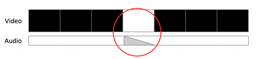
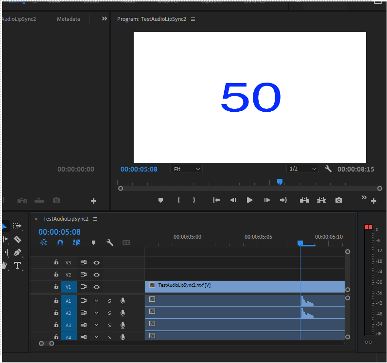
Using an NLE (or other reliable software), check whether video and audio are in sync. The clapperboard sound should start within the white frame, close to the start of the white frame. See the figure below.
If audio and video are not in sync, tweak the server room gear accordingly and repeat the test until satisfied.
Calibration A6: Audio mixer command latency
The goal of this test is to measure audio mixer command latency: the time it takes the audio mixer to respond to a fader command.
What is the plan?
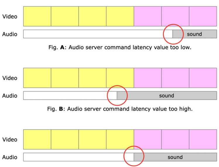
Take a silent yellow clip, followed by a pink clip with full sound right from the first frame, while PGM is recorded. Looking at the cut in the recording using a quality NLE, audio should show up exactly at the start of the first pink frame. Any audio mixer command latency makes the audio show up delayed compared to the first pink frame.
Test material and gear
Rundown:
Calibration-A6. See Rundown recipes above.A video recorder recording the PGM output. Story Recorder works too.
Harmonic's Clip Tool, or a serious NLE such as Premiere Pro or Final Cut Pro.
Test
On the AV Automation Genlock tab, make sure that video server command latency is calibrated and specified.
On the AV Automation Genlock tab, make sure the switcher command latency value is calibrated and specified.
On the AV Automation Genlock tab, make sure the audio command latency value is set to 0 ms.
Start the video recorder to record the PGM output.
Start the rundown and take story by story.
Once the rundown has ended, open the recorded video in Clip Tool or an NLE.
Find the location in the recording where the silent yellow clip cuts into the pink clip with sine wave sound. The audio should start right at the first pink frame.
Using Clip Tool or the NLE, find out where the audio really starts relative to the first pink frame. Do this by ear, stepping through the frames, or visually, by looking at the audio track in the NLE.
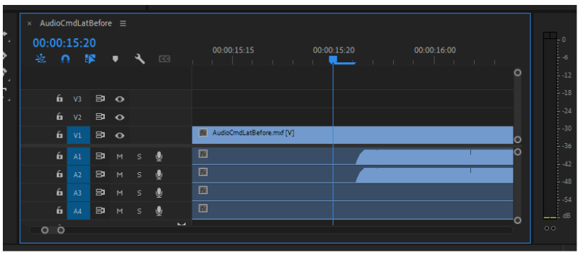
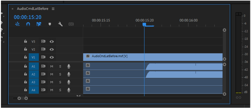
If the audio is late, increase the audio mixer command latency setting on the AV Automation Genlock tab and repeat the test. See Figure 13 below.
If the audio is early, decrease the audio mixer command latency setting and repeat the test. See Figure 14 below.
If the audio starts at the beginning of the first pink frame, the test is successful.
Repeat the test several times to confirm consistent behavior.
B-series calibration tests: alternative tests
Calibration B2: Video server command latency
This test is an alternative to the recommended A2 test.
This test measures the video server command latency, which is the time it takes the video server to respond to a Play command, expressed in frames. Perform the test for each of the individual video server ports involved in the playout of rundown clips.
Test A2 is preferred over this one, because this test depends on the switcher command latency while that value has not been calibrated yet. Instead, this test assumes a switcher command latency of 1 frame, which is a good guess. Use this test if you cannot run test A2, which requires a video recorder.
What is the plan?
Take a yellow clip, followed by a black clip with numbered frames, where the first frame is white. Record the session on a mobile phone from a monitor. Set the video server latency initially very high, which causes Viz Mosart to wait too long for the clip to play. As a result, the video server is already playing well into the clip once it is taken on PGM. The number in the first non-yellow frame in the recording indicates how many frames were waited too long.
Test material and gear
Rundown:
Calibration-B2. See Rundown recipes above.A mobile phone for recording the PGM output from a monitor.
Test
Make sure cabling is restored to normal.
On the AV Automation Genlock tab, set the video server command latency to 20 frames.
On the AV Automation Genlock tab, set the switcher command latency to 1 frame.
With a mobile phone, record a video of a monitor showing the PGM output.
Load and start the rundown. Take story by story until the last one.
Once you see the blue numbers on the black background, stop the video recording.
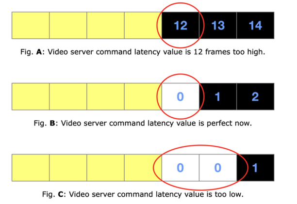
On the phone, find the very first non-yellow frame in the recorded video. It shows a number, for example 12. This is the number of frames waited too long for the video server. See Figure 15A below.
On the AV Automation Genlock tab, set video server command latency to 20 minus the number found. In this example, that results in 8.
Reload the rundown and repeat the test.
The first non-yellow frame should be a single white frame, followed by black frames, as shown in Figure 15B below. In all other cases the test failed, so retry.
Repeat this test for the other video ports involved in video playout, by changing the templates.
Note: All these ports should produce the same latency value.
Having found the latency value, repeat this test a few more times to confirm consistent behavior. In all cases a single white frame followed by black frames should be the result.