Service Host Administrator Guide
Version 1.3 | Published August 14, 2019 ©
Channel Recorder Configuration
You can configure Channel Recorder at any time after successfully registering an instance. For any configuration changes to take effect, you must restart the instance. Every plugin of Service Host has its own configuration page. For more information, refer to the Service Host Administrator Guide documentation.
Every plugin configuration page consist of two main sections:
The Plugin Configuration Section is unique for each plugin. From the Service Host Section, you can set specific command arguments to the plugin. This is useful mainly for debugging purposes.
Plugin Configuration Section
The Plugin Configuration Section consists of the following parts:
-
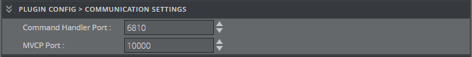
Communication Settings
-
Command Handler Port: Selects the port used to communicate with Channel Recorder via Viz Send. The default value is 6810.
-
MVCP Port: Selects the port used to communicate with Channel Recorder using MVCP. Some Vizrt components, such as Ingest, Dart or Capture, use this protocol to communicate with Channel Recorder. The default value is 10000, while e.g. Ingest uses 5250 as default for its first channel and subsequent port numbers for any additional channels.
Tip: If several instances of Channel Recorder are present in the machine, the ports must be different for each.
-
-
Board Settings (changes to these settings only take effect by restarting the Channel Recorder instance).
-
Serial Number: Selects the board with the specified serial number. If no serial number is specified, the first detected board is selected. By default, no value is specified.
Tip: The serial number on Matrox video boards can be found in the hardware tab of Matrox X.info, it usually begins with an A.

-
-
Input Settings
-
Input: Selects the type of input to use. At the moment, only Video input is possible.

-
-
Video Input Settings
-
Connector: Selects the connector that will be used for recording live input. This is a required value. The default value is empty. Accepted values are A to H, depending on the input configuration of the Matrox board.
Tip: The ports for Matrox IP board indicate the SFP.

-
-
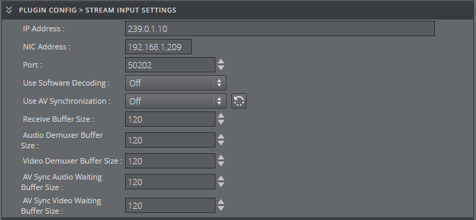
Stream Input Settings
-
IP Address: Indicates the source IP address.
-
NIC Address: Indicates which NIC is used for receiving the stream.
-
Port: Indicates the source port.
-
Use Software Decoding: Chooses between using the hardware or software decoder.
-
Use AV Synchronization: Enables audio and video synchronization of both are present. If only video is present this option must be disabled.
-
Receive Buffer Size: Indicates the size of the buffer of the RTP receiver. If performance is an issue this can be increased.
-
Audio Demuxer Buffer Size: Indicates the size of the audio demuxer buffer. If performance is an issue this can be increased.
-
Video Demuxer Buffer Size: Indicates the size of the video demuxer. If performance is an issue this can be increased.
-
AV Sync Audio Waiting Buffer Size: Indicates how much audio data it should have before synchronization is done. If sync is an issue this can be increased or decreased along with AV Sync Video Waiting Buffer Size.
-
AV Sync Video Waiting Buffer Size: Indicates how much video data it should have before synchronization is done. If sync is an issue this can be increased or decreased along with AV Sync Audio Waiting Buffer Size.
-
-
Process Settings
-
Priority: Sets the process priority class. The values correspond to the Windows process priority levels. The default value is Normal.

-
-
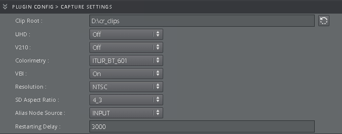
Capture Settings
-
Clip Root: Sets the default folder for the recordings. The default value is V:/.
-
UHD: Enables detection of UHDTV signals. When set to On , the Channel Recorder scans the signal resolution on the four corresponding input connectors. If four 3G signals are detected, they are interpreted as one UHDTV signal. When set to Off, the four connectors are treated as separate 3G signals. The default value is Off.
-
V210: Uses the 10-bit surface format V210. This is needed to record XAVC, it increases performance when for example recording ProRes. This surface format is not supported on the Matrox X.mio2+. The default value is Off.
-
Colorimetry: Specifies the colorimetry to be used to be able to record in HDR. By default ITUR_BT_601 will be used for SD resolution and ITUR_BT_709 for HD and UHD resolution.
-
VBI: Enables VBI recording. To capture closed caption this value must be set to On. The default value is On .
-
Resolution: Sets the default resolution. The possible values are: NTSC, PAL, 720p50, 720p60M, 1080i25, 1080p60, 1080i30M, 1080i30, 1080p50, 1080p60M and 1080p60. The default value is NTSC .
-
SD Aspect Ratio: Specifies the aspect ratio for SD resolution.
-
Alias Node Source:Specifies the source of the alias node which specify from which output or input connector the application will record.
-
Restarting Delay: Specifies the time in milliseconds before the channel is restarted after detecting a change in resolution.
-
-
Test Settings
-
Performance Test Mode: Selects the mode when a performance test is to be performed. The values are GENERATE and CONSUME. GENERATE will generate a RAW file using the input signal. CONSUME will read the generated file as fast as possible and send it for encoding. While using CONSUME mode calling RECORD PERFORMANCE GET will give you the maximum frame rate, which gives you how many recording can be run in the machine taking into account only the CPU usage. For example, if the value is 280 FPS using as input 720p, the machine can only do five recordings at 720p50.

-
-
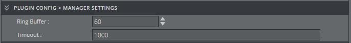
Manager Settings
-
Ring Buffer: Sets the size of the capture ringbuffer. The default value is 60.
-
Timeout: Sets the timeout for the capture operation in milliseconds. If the recorder reports timeout errors, increasing the timeout could help. The value can be in frames or in timecode format: 00:00:00:00. The default value is 1000.
-
-
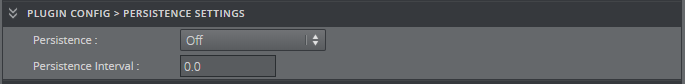
Persistence Settings
-
Persistence: Chooses if a backup of the scheduled recording is needed. This is only useful for scheduled recordings. The default value is Off.
-
Persistence Interval: Defines, in seconds, the interval in which the backup is written to disk. The default value is 0.
-
-
Log Settings
-
Timecode Log Interval: Specifies the interval at which the current timecode is logged. The value can either be a number of frames or a timecode-based relative value. The default value is 0, which means that every full second is logged.

-
-
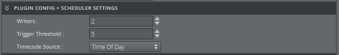
Scheduler Settings
-
Writers: Sets the number of writers to initialize. This value is only relevant in loop and scheduled recordings in which consecutive recordings are very close to each other within the timeline (less than six seconds). The default value is 2 and should never be below 2.
-
Trigger Threshold: Determines whether to execute a timed command late if it misses the execution time. If the time is still within the trigger threshold, it will be executed late. Outside of this window, the command is ignored until the next time the timecode is received. The value can either be a number of frames or a timecode-based relative value. The default value is 5.
-
Timecode Source: Specifies the timecode source. The default value is TIME_OF_DAY.
-
Inclusive Out: Writes the last timecode to the file at the defined out point of the recording when enabled.
-
-
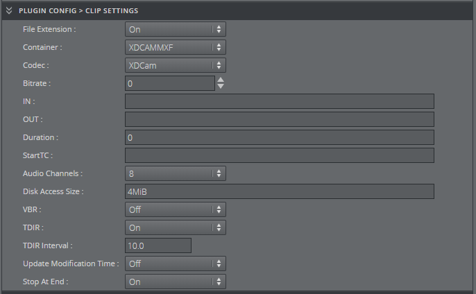
Clip Settings (these are the default values for any future recordings)
-
File Extensions: Enables or disables automatically adding a file extension to the file name. If this feature is turned off, the client application has full control over the file name. The default value is Off.
-
Container: Sets the container type of the recorded file. Possible values are AVCINTRAMXF, AVI, DVCPROMXF, MOV, MXF, XAVCMXF, XDCAMMXF. For capturing OP-Atom the value should be MXF. The default value is XDCAMMXF.
-
Codec: Sets the codec type of the recorded file. The possible values are: DvCam, DvCPro, Dv50, IFrame, XDCam, AVCIntra50, AVCIntra100, ProRes. The default value is XDCam which corresponds to XDCAM HD422.
-
Bitrate: Sets the bitrate for the video encoding in mbps (megabits per second). Not all codecs allow changes to the bitrate. In such cases, this value is ignored. The default value is 0.
-
IN: Sets the default value for the recording in point. The value must be in timecode format: 00:00:00:00.
-
OUT: Sets the default value for the recording out point. The value must be in timecode format: 00:00:00:00.
-
Duration: Sets the default duration of the recording. The default value is 0.
-
StartTC: Sets the default value for the starting timecode. The value must be in timecode format: 00:00:00:00.
-
Audio Channels: Sets the number of audio channels to record. How many channels are actually recorded depends on the codec and the input signal. The default value is 8.
Tip: Some formats have specific audio support, so even if the user specifies a higher or lower value, it will record always the same number of channels. Please refer to the documentation for each format.
-
Disk Access Size: Sets the size of data blocks written to the disk in bytes. Postfixes like KiB, Kb, k, etc., are allowed, but must not be separated from the value with a blank space. The default value is 4MiB (1*4194304 bytes). The minimum value is 32KiB (32768 bytes).
-
VBR: Sets whether the recorded file, when the format supports it, should be in VBR (Variable Bit Rate).
-
TDIR: Sets the default behavior of TDIR (Time Delayed Instant Replay). The default value is On .
-
TDIR Interval: Sets the interval of file header updates in TDIR recordings. The value is in seconds and fractions of seconds, meaning both 11.1 and 11.2 are considered valid values. Minimum allowed value is 10.0, which is interpreted by Channel Recorder as every frame. The maximum value is 60.0. The default value is 10.0.
-
Update Modification Time: Updates the modification time of the recorded clip regardless of TDIR setting value. The default value is On.
-
Stop At End: Sets the default value at the end of the recording. For loop and scheduled recordings this value should be Off. The default value is Off.
-
-
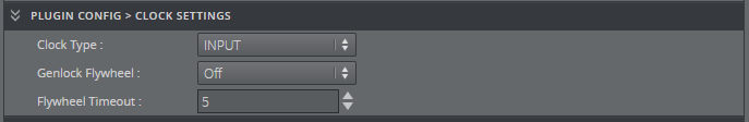
Clock Type: Defines what type of clock is used for recording. The possible values are: GENLOCK and INPUT. The default value is INPUT.
Tip: When recording without a signal, GENLOCK clock type is recommended due to the drift that INPUT clock type can cause. INPUT clock type is generally the better choice when a signal is present all the time while recording.
-
Genlock Flywheel: Uses the flywheel in case the genlock signal is lost if Clock Type is GENLOCK.
-
Flywheel Timeout: Sets the timeout of the genlock flywheel in seconds. This defines the time until the genlock switches to free run, as well as the maximum time the flywheel can use to resynchronize. The default value is 5.0.
-
-
Output Settings
-
Output: Specifies the output mode. The possible values are: VIDEO, CODER, NONE. The default value is NONE.
Tip: Only one type of output can be configured at startup using the web interface. However, after startup, it is still possible to configure another output via Viz Send.

-
-
Video Output Settings
-
Connector: Selects the connector that will be used for outputting the recorded frames. Accepted values are A to H, depending on the output configuration of the Matrox board.

-
-
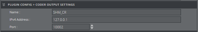
Coder Output Settings
-
Name: Sets the name of the shared memory.
-
IPv4 Address: Sets Viz Coder Recording Proxy IP address.
-
Port: Sets Viz Coder Recording Proxy port number.
-
-
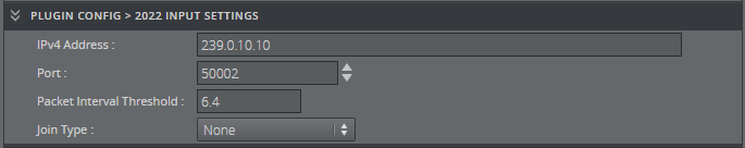
2022 Input Settings
-
IPv4 Address: Sets destination IPv4 address.
-
Port: Sets destination port.
-
Packet Interval Threshold: Indicates the threshold for generating the time interval between the IP packets alarm on the main IP stream. The range is from 6.4 nanoseconds to 419424.0 nanoseconds, in intervals of 6.4 nanoseconds.
-
Join Type: Indicates the type of membership request made when IPv4 address is a multicast address.
-
-
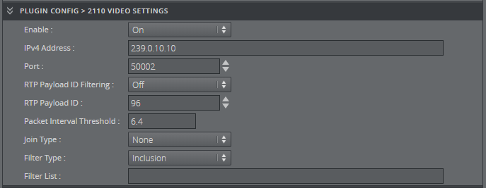
2110 Input Video Settings
-
Enable: Enables video flow when set to True.
-
IPv4 Address: Sets destination IPv4 address.
-
Port: Sets destination port.
-
RTP Payload ID Filtering: Uses the RTP Payload ID value to filter the incoming network packets when set to True.
-
RTP Payload ID: Indicates the RTP (Real-time Transfer Protocol) Payload ID to capture. Used when RTP Payload ID is set to True .
-
Packet Interval Threshold: Indicates the threshold for generating the time interval between the IP packets alarm on the main IP stream. For video, the range is from 6.4 nanoseconds to 419424.0 nanoseconds, in intervals of 6.4 nanoseconds.
-
Join Type: Indicates the type of membership request made when IPv4 address is a multicast address.
-
Filter Type: Specifies the type of filtering applied to the source list when IGMPv3 is used.
-
Filter List: Lists IPv4 addresses to be included or excluded, separated by a space character.
-
-
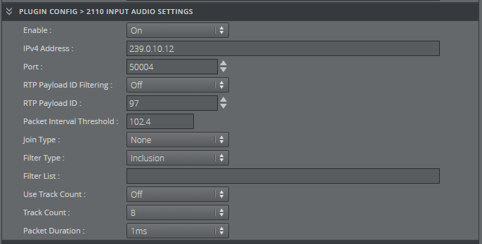
2110 Input Audio Settings
-
Enable: Enables audio flow when set to True.
-
IPv4 Address: Sets destination IPv4 address.
-
Port: Sets destination port.
-
RTP Payload ID Filtering: Uses the RTP Payload ID value to filter the incoming network packets when set to True.
-
RTP Payload ID: Indicates the RTP (Real-time Transfer Protocol) Payload ID to capture. Used when RTP Payload ID is set to True.
-
Packet Interval Threshold: Indicates the threshold for generating the time interval between the IP packets alarm on the main IP stream. For audio, the range is from 102.4 nanoseconds to 6710681.6 nanoseconds in intervals of 102.4 nanoseconds.
-
Join Type: Indicates the type of membership request made when IPv4 address is a multicast address.
-
Filter Type: Specifies the type of filtering applied to the source list when IGMPv3 is used.
-
Filter List: Lists IPv4 addresses to be included or excluded separated by a space character.
-
Use Track Count: Uses track count to specify the number of tracks for the incoming IP stream when set to True.
-
Track Count: Specifies the number of tracks for the incoming IP stream.
-
Packet Duration: Indicates the duration of the incoming audio packet. The packet size (in samples) can be computed using the sample rate (48000 samples/sec) and the packet duration.
-
-
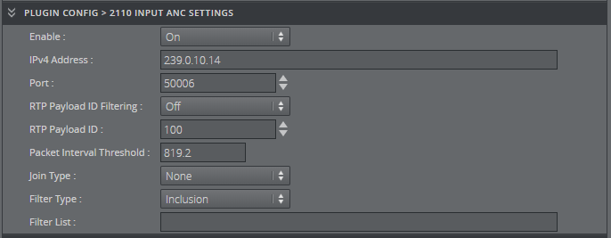
2110 Input ANC Settings
-
Enable: Enables ANC flow when set to True.
-
IPv4 Address: Sets destination IPv4 address.
-
Port: Sets destination port.
-
RTP Payload ID Filtering: Uses the RTP Payload ID value to filter the incoming network packets when set to True.
-
RTP Payload ID: Indicates the RTP (Real-time Transfer Protocol) Payload ID to capture. Used when RTP Payload ID is set to True.
-
Packet Interval Threshold: Indicates the threshold for generating the time interval between the IP packets alarm on the main IP stream. For ancillary data, the range is from 819.2 nanoseconds to 53685452.8 nanoseconds in intervals of 819.2 nanoseconds.
-
Join Type: Indicates the type of membership request made when IPv4 address is a multicast address.
-
Filter Type: Specifies the type of filtering applied to the source list when IGMPv3 is used.
-
Filter List: Lists IPv4 addresses to be included or excluded separated by a space character.
-
-
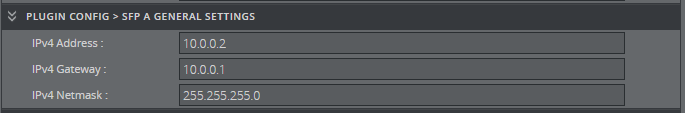
SFP A General Settings
-
IPv4 Address: Sets IPv4 address.
-
IPv4 Gateway: Sets IPv4 gateway.
-
IPv4 Netmask: Sets IPv4 netmask.
-
-
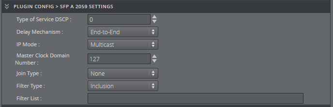
SFP A 2059 Settings
-
Type of Service DSCP: Specifies a datagram's priority and requests a route for low-delay, high-throughput, or highly-reliable service.
-
Delay Mechanism: Specifies the type of network delay mechanism to use for the time server connection.
-
IP Mode: Specifies the type of internet protocol mode to use for the time server connection.
-
Master Clock Domain Number: Specifies the master clock domain number.
-
Join Type: Indicates the type of membership request made when IPv4 address is a multicast address.
-
Filter Type: Specifies the type of filtering applied to the source list when IGMPv3 is used.
-
Filter List: Lists IPv4 addresses to be included or excluded separated by a space character.
-
-
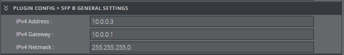
SFP B General Settings
-
IPv4 Address: Sets IPv4 address.
-
IPv4 Gateway: Sets IPv4 gateway.
-
IPv4 Netmask: Sets IPv4 netmask.
-
-
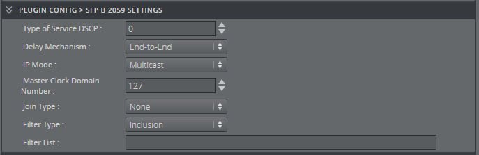
SFP B 2059 Settings
-
Type of Service DSCP: Specifies a datagram's priority and requests a route for low-delay, high-throughput, or highly-reliable service.
-
Delay Mechanism: Specifies the type of network delay mechanism to use for the time server connection.
-
IP Mode: Specifies the type of internet protocol mode to use for the time server connection.
-
Master Clock Domain Number: Specifies the master clock domain number.
-
Join Type: Indicates the type of membership request made when IPv4 address is a multicast address.
-
Filter Type: Specifies the type of filtering applied to the source list when IGMPv3 is used.
-
Filter List: Lists IPv4 addresses to be included or excluded separated by a space character.
-
-
2059 Settings
-
Best Master Selection: Specifies the BMCA (Best Master Clock Algorithm) used to select the genlock over IP signal.

-
-
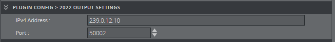
2022 Output Settings
-
IPv4 Address: Sets destination IPv4 address.
-
Port: Sets destination port.
-
-
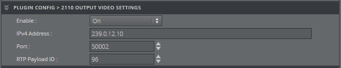
2110 Output Video Settings
-
Enable: Enables video flow when set to True.
-
IPv4 Address: Sets destination IPv4 address.
-
Port: Sets destination port.
-
RTP Payload ID: Indicates the RTP (Real-time Transfer Protocol) Payload ID to capture. Used when RTP Payload ID is set to True.
-
-
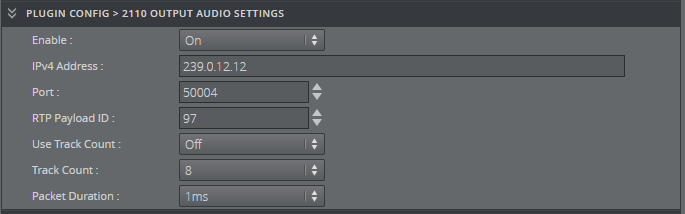
2110 Output Audio Settings
-
Enable: Enables audio flow when set to True.
-
IPv4 Address: Sets destination IPv4 address.
-
Port: Sets destination port.
-
RTP Payload ID: Indicates the RTP (Real-time Transfer Protocol) Payload ID to capture. Used when RTP Payload ID is set to True.
-
Use Track Count: Uses track count to specify the number of tracks for the outgoing IP stream when set to True.
-
Track Count: Specifies the number of tracks for the incoming IP stream.
-
Packet Duration: Indicates the duration of the incoming audio packet. The packet size (in samples) can be computed using the sample rate (48000 samples/sec) and the packet duration.
-
-
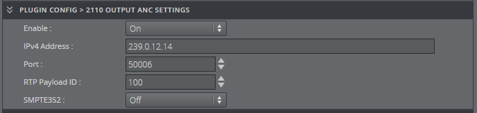
2110 Output ANC Settings
-
Enable: Enables ANC flow when set to True.
-
IPv4 Address: Sets destination IPv4 address.
-
Port: Sets destination port.
-
RTP Payload ID: Indicates the RTP (Real-time Transfer Protocol) Payload ID to capture. Used when RTP Payload ID is set to True.
-
SMPTE352: Enables SMPTE 352 packets when set to True.
-
-
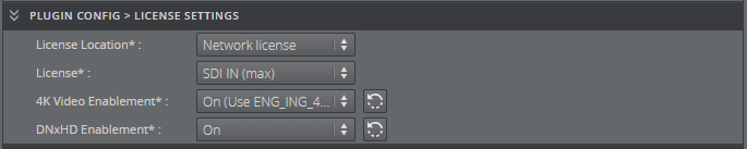
License Settings
-
License Location: Defines where the WIBU license is located. This can be network or local if the user has a file or a WIBU dongle attached.
-
License: Defines the license type. If the use does not have SDI IN (max). Demo option can be used, however the recordings will have 100 black frames every 400 frames.
-
4K Video Enablement: Enables 4K video license fetching. If none is found the user will not be able to start Channel Recorder. If already recording and the license is not accessible or expired, the user will have 100 black frames every 400 frames.
-
DNxHD Enablement: Enables DNxHD license fetching. If none is found the user will not be able to start Channel Recorder. If already recording and the license is not accessible or expired, the user will have 100 black frames every 400 frames.
-
Service Host Section
Only one setting can be set in this section:
-
Arguments: Specifies the arguments that are going to be passed to Channel Recorder.
An example of a string that can be used for enabling log level debug is: -v -l debug -n 10 -m 50
Note: Channel Recorder 1.2 introduces two new parameters: n and m . n specifies the maximum number of log files and m the maximum size of each log file in MB. By default, the number of log files is four and the maximum size of each log file is 10 MB.
See Also