Service Host Administrator Guide
Version 1.3 | Published August 14, 2019 ©
Integration with Other Services
Channel Recorder can be integrated with other services.
Viz Capture
The Viz Capture video acquisition tool can be configured to acquire assets using Channel Recorder. Integration of Channel Recorder with Viz Capture is based on the MLT Video Control Protocol, or MVCP. MVCP is activated on port 10000 by default. To change the port, refer to Channel Recorder Configuration.
For using Channel Recorder with VizCapture the following settings are specially important:
-
Inclusive Out: By default, Channel Recorder does not record the last frame specified by Viz Capture. This must be changed to 1 if the value in Viz Capture application should match the recorded frames timecode.
-
Timecode Source: When using VizCapture this value should be changed to VITC or LTC.
For further information on how to configure Viz Capture, or how to operate it on a Video Disk Recorder, refer to the Viz Capture Documentation.
Viz Dart
The Viz Dart video acquisition tool can be configured to acquire assets using Channel Recorder. Integration of Channel Recorder with Viz Dart is based on the MLT Video Control Protocol, or MVCP. MVCP is by default activated on port 10000. To change the port, refer to Channel Recorder Configuration.
When operating Viz Dart with Channel Recorder, the timing between the different components is important. Take the following example:
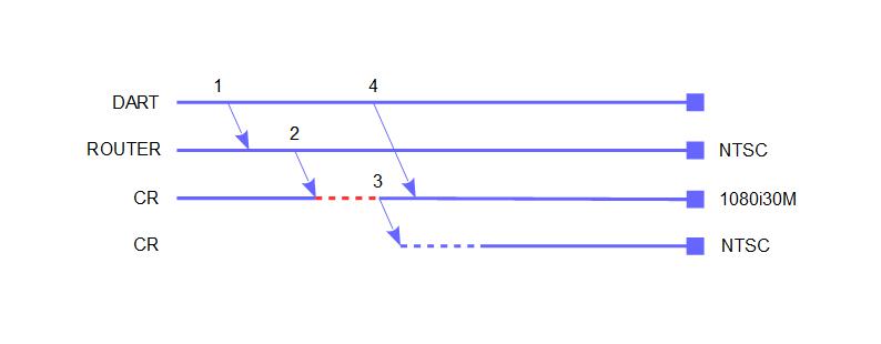
The typical operation when using Viz Dart is as follows:
-
Dart sends a command to the router to route an NTSC signal to Channel Recorder.
-
The router sends the NTSC signal to Channel Recorder.
-
Channel Recorder was configured as 1080i30M, so it triggers a configurable timeout (dotted red line).
-
By default, this timeout is three seconds duration and can be configured (restarting_delay).
-
After the timeout, Channel Recorder restarts with NTSC signal resolution.
-
If the same signal as configured (.i.e 1080i30M) is received again within those three seconds, the restart is cancelled.
-
-
During the restart (dotted blue line) it is possible that Dart sends the MVCP commands to schedule a recording. If this happens, Channel Recorder queues the commands until it is ready with the new resolution.
There are other several situations (this is not meant to be an exhaustive list, but rather some examples):
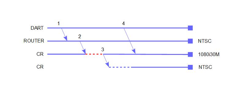
In this case, the MVCP commands are sent after the restart has already finished.
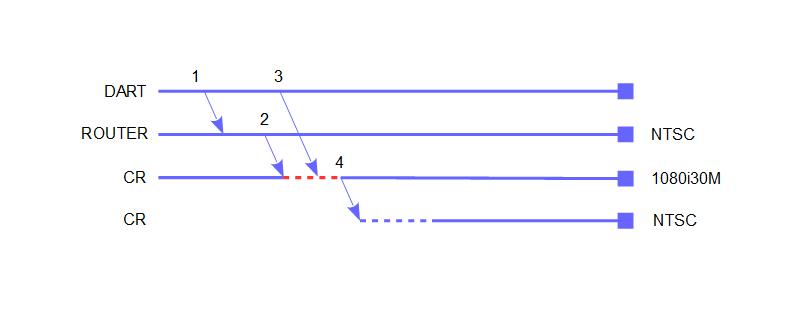
In this case, the MVCP commands are sent before the restart occurred. When the restart finishes Channel Recorder recovers the timeline created before the restart.
Another important thing to consider is when Dart is configured with trigger_duration_out: 0. This configuration means that Dart does not send /SEQA SET UX MED vtr.media.input.trigger.duration.out to Channel Recorder and instead manually stops the recording by sending STOP UX.
One of the common issue with this configuration is that Channel Recorder is stopped unexpectedly (Dart reports this as "REC Unexpected DONE or BUSY state"). This is because Channel Recorder has received /SEQA SET UX MED vtr.media.input.trigger.duration.out before and is using the duration for all other recordings. So recordings that are longer than the specified duration are now going to be failing because Channel Recorder stop them at the configured duration instead of when Dart send the STOP UX command. One thing to note is that this duration is persistent among recordings.
Viz Dart also offers some configuration options, such as when the MVCP commands should be sent (prestarttime). To see the other options, use the following command on the Viz Dart machine: /opt/dart/bin/editconf -ey dartsettings.
For further information on how to configure Viz Dart, or how to operate it on a Video Disk Recorder, refer to the Viz Dart Documentation.
Coder
Coder is the next generation transcoder that can be used as a standalone component with Viz Engine, or in a MAM environment using Viz One. To setup the Channel Recorder to output to Coder, issue the following command:
CONFIG SET SHMOUT SHMNAME [shared memory name]CONFIG SET SHMOUT ADDRESS [proxy hostname]CONFIG SET SHMOUT PORT [proxy port]OUTPUT START CoderAlternatively, the output can be started automatically during startup. Refer to Output Settings in Channel Recorder Configuration.
[proxy hostname] and [proxy port] are only used by Viz Coder Recording Proxy and are not necessary. This application automatically creates a job for Coder and transcodes using the setting specified in an XML file bundled with the application. If the Viz Coder Recording Proxy is not used, [proxy hostname] and [proxy port] can be left out.
To be able to use Coder with Channel Recorder in a new machine, follow these steps:
-
Install Viz Coder.
-
Go to C:\Program Files (x86)\vizrt\Coder and run coder_slave.exe in the command prompt with Administrator privileges:
register_slave.exe http://[IP]:[Port]Where [IP] IP address where Coder is installed (if in doubt use the localhost IP) and [Port] is the port that Coder is using (if in doubt use 8081 which is the default value of Coder port).
-
Go to C:\ProgramData\Microsoft\Windows\Start Menu\Programs\Vizrt\Coder and run run_benchmark.exe by double clicking on it.
Warning: Do not run run_benchmark.exe from C:\Program Files (x86)\vizrt\Coder, since this does not work.
The port used by Coder can be checked in C:\ProgramData\vizrt\Coder\vizrt-coder-master.log.
-
Go to Coder web interface http://[IP]:[Port]/ui/war/index.html (e.g. http://localhost:8081/ui/war/index.html) and check if the slave worker is there by clicking the Workers tab.
-
Create a new live job with the following setting:
-
Input URL: shm://@[IP]:[shared memory name] where [IP] is the IP address where Channel Recorder is located and [shared memory name] is the shared memory name given in the configuration without the Global\ string.
Note: To use Coder the shared memory name given in the configuration of Channel Recorder must be preceded by Global\ this is because Coder always expects the shared memory to be located in the Global namespace.
-
Output URL: udp://@[IP]:[Port] where [IP] and [Port] is the IP address and port where the stream is going to be sent.
-
Profile URL: mpegts_mpeg2_720p.
Note: The settings above are just example and can be changed, however it is recommended to test with these values first before experimenting with other values.
-
To test that the above steps are done correctly, open VLC and go to Media > Open Network Stream and use the address specified in Output URL when Channel Recorder is recording and using the appropriate configuration. Example of configuration for Coder:
<field name="coder-output-settings"> <field name="name"> <value>Global\viz_shm_cr_01</value> </field> <field name="ipv4address"> <value>127.0.0.1</value> </field> <field name="port"> <value>10002</value> </field> </field>Please note that Global\ is used for the name of the shared memory. For the Input URL only viz_shm_cr_01 should be given.
For further information on the configuration and operation of Coder, refer to the Media Service documentation.
See Also
-
Media Service documentation
-
Viz One documentation for Viz Dart