
Tracking Hub Administrator Guide
Version 1.4 | Published October 30, 2020 ©
Preview Panel
This page contains information about the following topics:
The 3D Preview panel gives a preview of the tracked cameras, which should be as close to the real studio as possible. When the Studio Manager starts up, a Parameter Service is established, which sends the positions of all tracked rigs to the preview panel.
The preview panel consists of the following parts:
-
The main menu.
-
The navigation bar.
-
The HUD display.
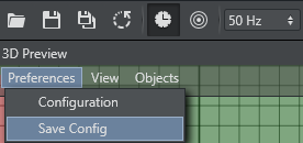
Preferences Menu
-
Configuration: Opens the Color Configuration window.
-
Save Config: Saves changes made in the configuration.
Configuration
In this window, the user can adjust the render colors for the visible objects in the preview panel. Click in a drop-down list to open the color selection window. The RGB and Alpha values can be adjusted for all colors, by clicking the Advanced button.
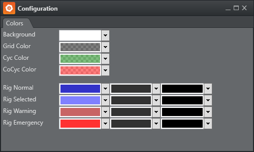
For the Background, Grid, Cyc and CoCyc colors, only diffuse color can be selected. These objects are rendered without lighting.
-
Rig Normal: Shows colors used when the Rig is not selected. The user can define Diffuse, Ambient and Shininess colors.
-
Rig Selected: Shows colors used when the Rig is selected in the Rig Editor.
-
Rig Warning: Shows when a connected Parameter service reports a problem which is handled by the system (interpolation of missing packages).
-
Rig Emergency: Shows when a Parameter service reports a problem which cannot be handled by the system, and immediate action from the operator is needed.
View Menu
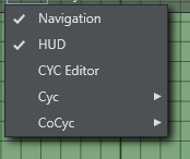
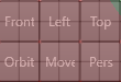
Navigation
Activates or deactivates the navigation bar in the bottom left corner of the 3D Preview window:
-
Front: Activates an orthographic camera, which looks in Z-Direction.
-
Right Mouse: Moves the camera in X and Y.
-
Mouse Wheel: Zooms in and out.
-
Middle Mouse: Moves the camera in X and Y.
-
-
Left: Activates an orthographic camera which looks in X-Direction.
-
Right Mouse: Moves the camera in Z and Y.
-
Mouse Wheel: Zooms in and out.
-
Middle Mouse: Moves the camera in Z and Y.
-
-
Top: Activates an orthographic camera which looks in Y-Direction
-
Right Mouse: Moves the camera in X and Z.
-
Mouse Wheel: Zooms in and out.
-
Middle Mouse: Moves the camera in X and Z.
-
-
Orbit: Activates a perspective camera which is fixed to the selected tracking system. This enables the user to modify handles even when the camera is moving.
-
Right Mouse: Rotates the camera around the rig.
-
Mouse Wheel: Zooms in and out.
-
Middle Mouse: Moves the camera in rig direction or away from the rig.
-
-
Move: Adjusts the relative camera position when no middle mouse button is present. Adjust by pressing the Move button and dragging the mouse.
-
Pers: Activates a perspective camera which is not bound to a Rig.
-
Right Mouse: Pans or tilts the camera.
-
Mouse Wheel: Zooms in and out.
-
Middle Mouse: Moves the camera in X and Z direction.
-
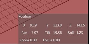
HUD
Activates the head up display, which displays the tracked raw coordinates of the selected rig.
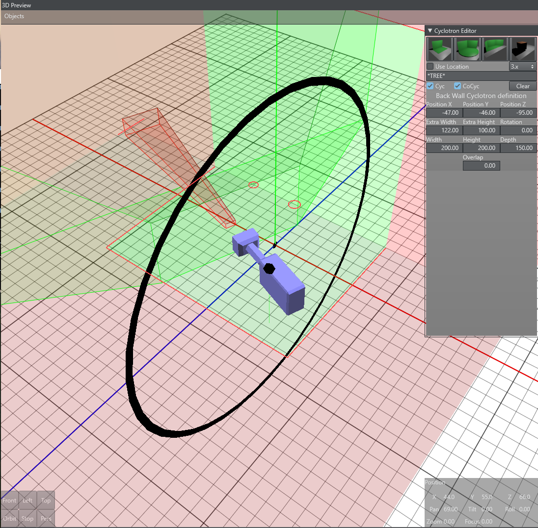
Cyclotron Editor
The CYC Editor enables creation of Cyc and CoCyc masks which are needed to mask out regions of the Studio not covered by the green/blue screen. The CoCyc mask is a geometry which is created in the CYC Editor and stored on the Tracking Hub. From there the CoCyc is sent to all connected Engines. Every change in the editor and its sub elements is immediately communicated to the Engines and to the Tracking Hub.
A new Cyclotron Editor (Cyc Editor) was introduced in version 1.2. Many customers were used to the old VizIO Cyc editor and were satisfied with the functionality. This feature is back in Studio Manager, and at the moment, the two Cyc definition methods coexist together.
Workflows
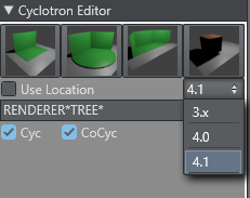
A new Cyc workflow was introduced in Viz Engine version 4.0. The Cyc resides now in a special scene property, which resides in the Virtual Studio scene. Please read the Viz Engine documentation for further information. As the transportation of the Cyc information sent to the Engines is different now, there is a new dropdown in the Cyc Editor to select the used Viz Engine version.
Please remember, that the Engine needs to be On Air to make the sent commands work.
The new Cyc Editor is located in the top-right corner of the preview panel. It can be expanded by clicking the arrow on the left side.
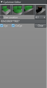
There are three Cyclotron types are available: Back-Wall, One-Corner and Two-Corner Cyc.
Common Cyc-Editor Elements
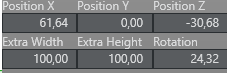
For every Cyc model, six common parameters can be defined. The position, rotation (Y-Axis), Extra Height and Extra Width. Extra height defines the distance from the top of the Cyc wall to the ceiling of the room. Extra width defines room size around the green wall and floor area.
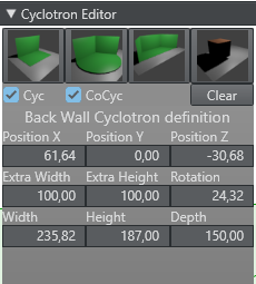
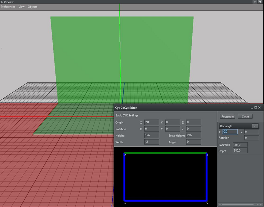
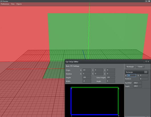
Back-Wall
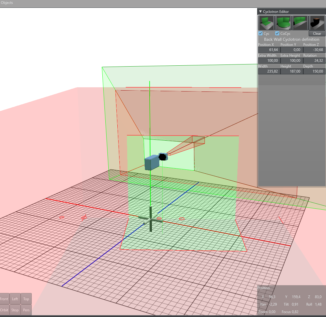
The back-wall Cyc has three additional parameters: These are the width of the green wall, height of the green wall and the depth of the ground area.
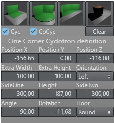
One Corner
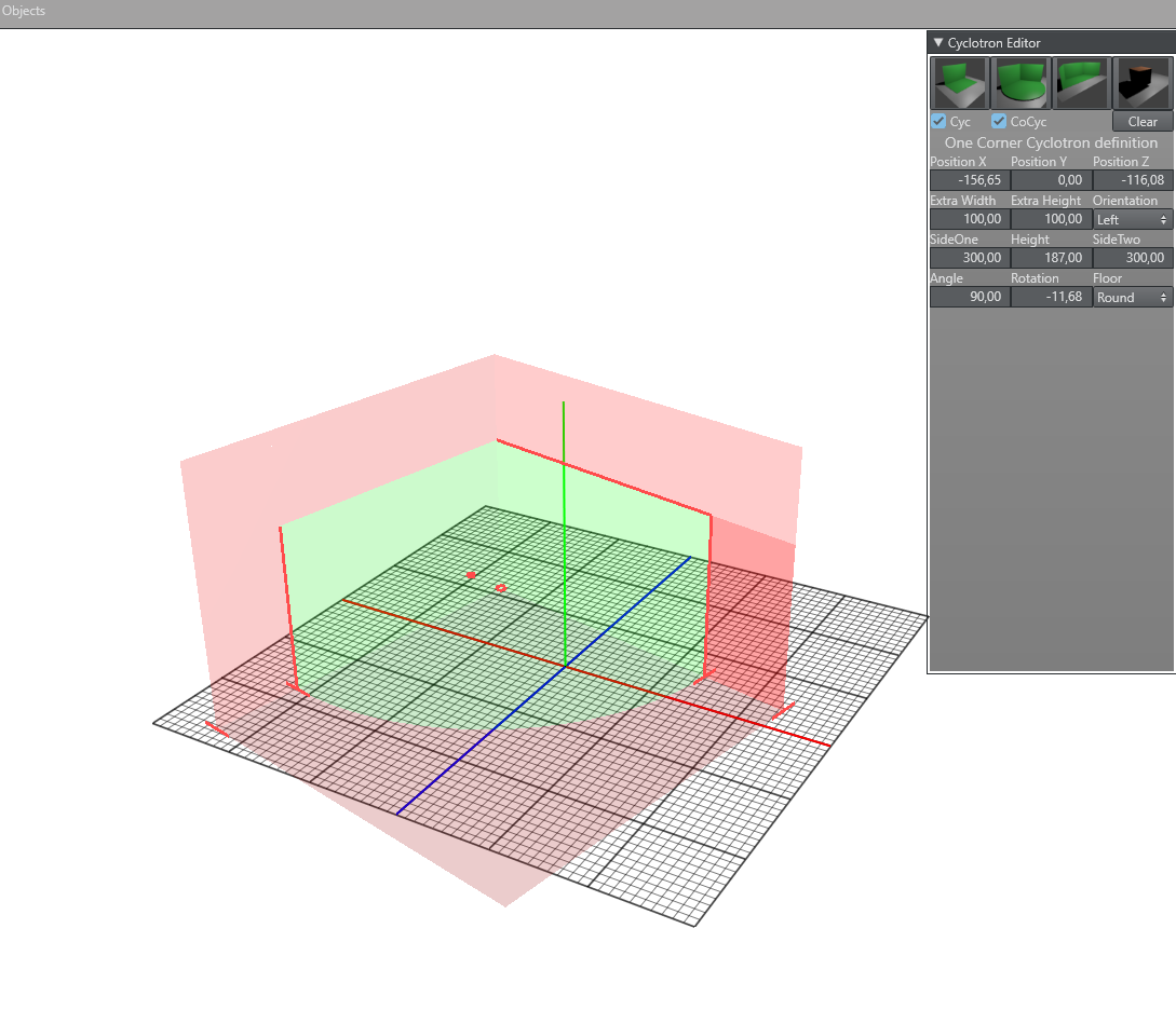
The One Corner Cyc is defined by two sides (side one and side two) and an opening angle. Additionally, the shape of the ground plane can be selected. The user can choose Round, Straight and Rectangular form.
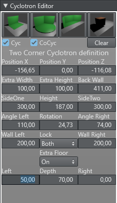
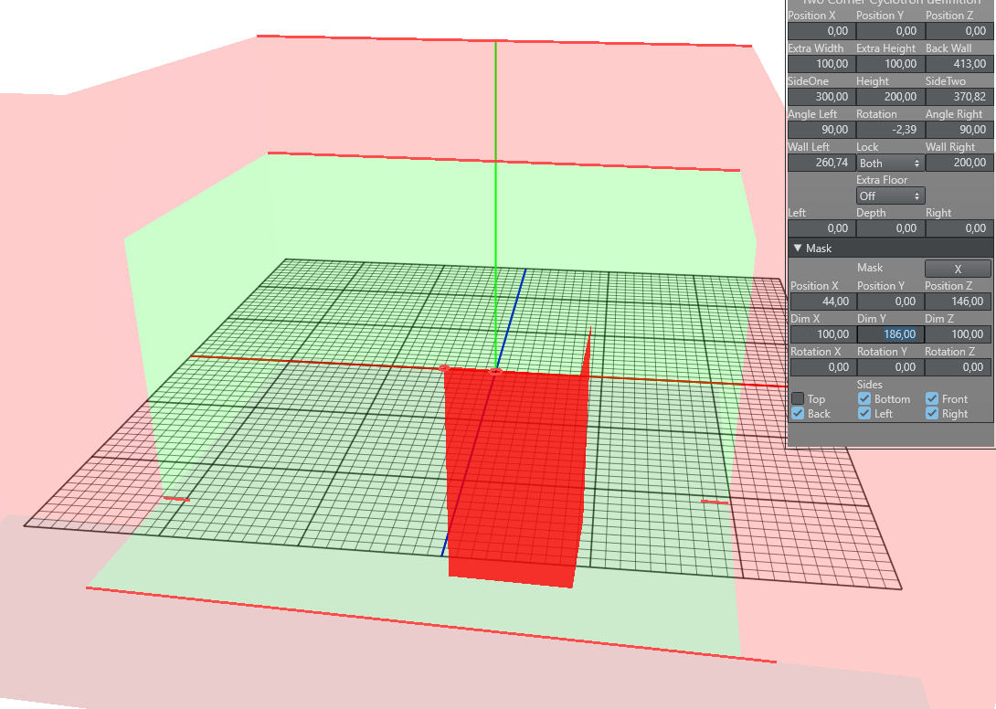
Two Corner
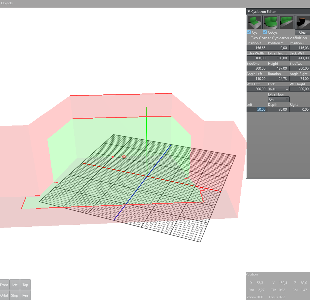
The Two Corner Cyc is defined by the length of SideOne and SideTwo, two opening angles (AngleLeft and AngleRight). It is possible to define the green area of the sides shorter than the side itself. This can be done with the parameters Wall Left and Wall Right. It is also possible to define an extra floor area. This extra floor is added in front of the green walls and extends the shape of the floor.
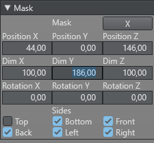
Masks
For any CYC model, any amount of Masks can be added. Masks are elements which will be added to the CoCyc walls. For any mask element the position, scale and rotation can be defined in the Cyc Editor. It is also possible to select for every sides of the cube if it should be rendered or not. In the tracking hub, the amount of masks is not limited.
The second option to define a Cyc/CoCyc is described below. Important to know is, that as soon as the user selects the old method, the new definition is deleted and vise versa.
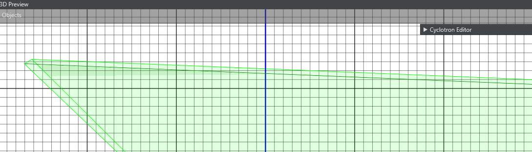
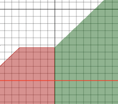
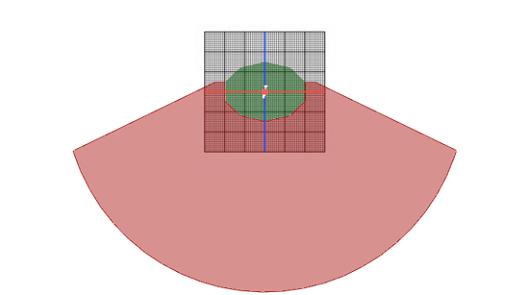
In Tracking Hub and the Studio Manager, a Cyc is defined by basic shapes, such as rectangles and circles, which can be added to a Shape List. All the shapes in the list are united by a Boolean operation which results in a segment list. The segment list is displayed in the segment area. From all these segments, a continuous subgroup can be selected in the editor to define if the segment is part of the green/blue wall or not. Every segment not selected (blue) is part of the floor. Every segment which is selected (green) is part of the Cyc wall. Based on this information, the Studio Manager is able to calculate a mask object which is then sent to Viz Engine.
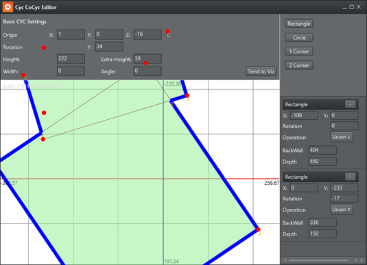
The Cyc Editor consists of the following Areas
-
Origin: Defines the X,Y,Z offset of the generated cyc with respect to the origin of the Viz Engine coordinate system.
-
Rotation: Defines the X,Y,Z rotation offset of the generated cyc with respect to the Viz Engine coordinate system.
-
Height: Defines the height of the green wall.
-
Extra Height: Defines the height of the studio ceiling.
-
Angle: See next section.
-
Width: See next section.
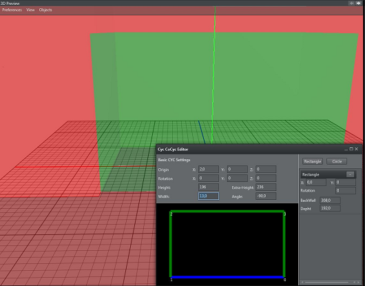
CyC Editor Angle and Width
The CYC generation algorithm works as follows:
-
Find a continuous group of wall segments and mark the start and end segment.
-
Calculate the normal of the last segment which is not part of the wall group.
-
Calculate the direction of the first segment, which is a wall.
-
Extrude the CoCyc for Width cm in the calculated normal direction.
-
Continue the extrude in direction of the first wall segment plus Angle.
-
Do the same with the end segment of the continuous group.
-
Close the CoCyc with a big surrounding circular object.
Examples
|
Example |
Description |
|
|
A simple back wall studio with one green wall. |
|
|
A corner studio with rectangular floor. |
|
|
A studio with three walls and rectangular floor. |
|
|
A studio with circular end floor. |
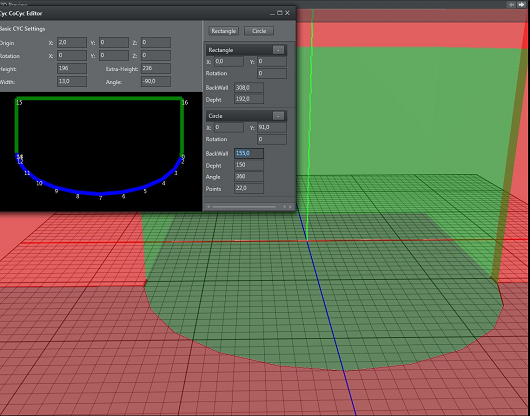
Shape Area
In the shape area, basic shapes can be added to the shape list. Every list elements shows a dash (-) in the Header line. Clicking on the dash (-) removes the shape from the list. Every shape can have its own origin and rotation about the Y axis. Additionally, every shape has its own parameters.
-
Rectangle
-
Back Wall: Sets the width of the rectangle in centimeters.
-
Depth: Sets the depth of the rectangle in centimeters.
-
-
Circle
-
Back Wall: Sets the width of the circle in centimeters.
-
Depth: Sets the depth of the circle in centimeters.
-
Angle: Defines the angle of the pie the shape creates, if smaller than 360.
-
Points: Sets the amount of segments the shape consists of.
-
Cyc
Defines what parts of the Cyc the preview panel renders. The selectable elements are Wall and Floor. All these settings are stored for local use in the user settings folder.
CoCyc
Defines what parts of the CoCyc the preview panel renders.
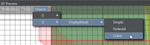
Objects Menu
Every rig present in Tracking Hub has its own display menu with it. These options are handled in the Object menu item. In the first release, Tracking Hub offered only one Rig: Simple Camera. In future releases, more rigs will be added to allow creating Cranes and other geometries.
-
l1 / l2 / l3: Selects which Rig to use.
Selectable Display Modes
|
Mode |
Description |
Example |
|
Simple |
The tracked point is displayed as selectable circle in the view. A rendered camera shows the offset settings. |
|
|
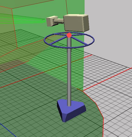
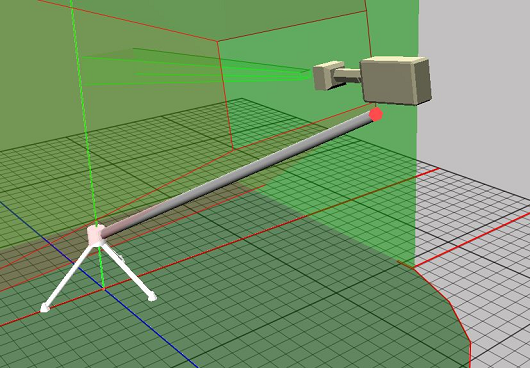
Pedestal |
The rig is displayed as a tracked pedestal. The tracking point is always on top of the pan/tilt head. The rendered camera shows the offsets added to the rig. |
|
|
Crane |
The rig is displayed as small jib. The origin of the base is the X/Z offset of the rig. The tracked point is a result of offset and height. |
|
|
Object |
Object is a tracked object which is not a camera. E.g. Motion Analysis objects. No camera is rendered and only the tracked point is displayed. |
|
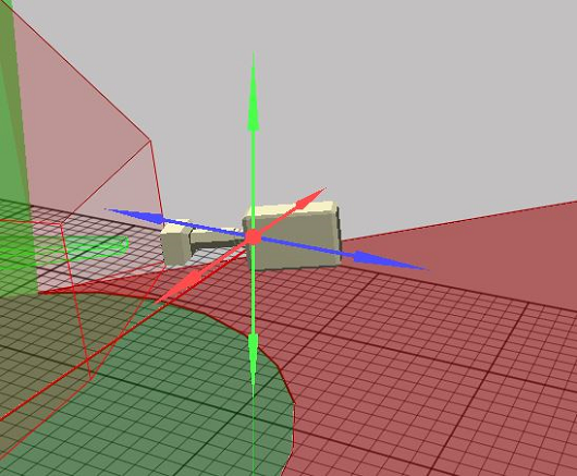
Camera Handles
Whenever the user clicks in the rig editor to adjust a specific value, the preview panel displays the values as a handle that can be dragged. Handles can be arrows (position) or disks (rotation). Whenever the user touches a Handle with the mouse, the handle goes from its base color to yellow. This indicates that only this handle is active at the moment. Clicking with the left mouse button and moving the mouse in handle or in the opposite direction modifies the handle's value.
The following list shows all available handles and the corresponding rig values.
|
Rig Value |
Description |
Example |
|
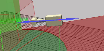
Position Offset |
Every axis is color coded and only visible if modifiable.
|
|
|
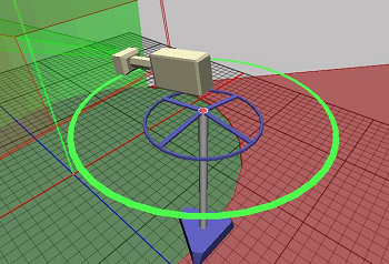
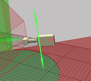
Pan Offset |
Green: Modifies the pan offset of the camera. |
|
|
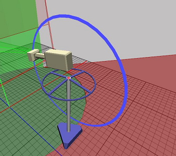
Tilt Offset |
Blue: Modifies the tilt offset of the camera. |
|
|
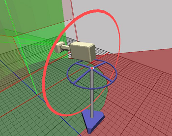
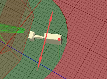
Roll Offset |
Red: Modifies the roll of the rig. |
|
|
Front Lens Shift |
Blue: Shows the distance from the CCD to the rotation axis of the tracking system. |
|
|
Height Lens Shift |
Green: Displays the distance from the CCD to the tilt axis of the tracking system. |
|
|
Right Lens Shift |
Red: Displays the distance from the CCD to the rotation axis in X direction. |
|

See Also