
Tracking Hub Administrator Guide
Version 1.4 | Published October 30, 2020 ©
Tracking Hub Structural Design
This section covers the following topics:
Protocol
The Protocol defines the data format sent from a tracking system to the Tracking Hub. It is independent from the transmission media and the geometry of the tracking system. The protocol generates tracked and named parameters, which are collected in the parameter pool. Protocols can be hard-coded in the Tracking Hub (like Motion Analysis), or as DLL files written with the plug-in API (available from version 2.0).
The XML Protocol Description was introduced in Tracking Hub 1.1. This protocol driver reads an XML file from either the hard drive or Graphic Hub. Out of this description, a parameter parser is generated which is able to read the data stream from the tracking system and translate it to named parameters, which are then sent to the Parameter Pool.
Parameters
A Parameter is a measured value of an encoder. It is extracted by the Protocol classes out of the Protocol data stream, the parameter is created by the Protocol. Its name is taken from the protocol description. The parameters in Tracking Hub are then converted from raw encoder values to human readable values, for example, the tick counts of a pan or tilt head are converted to degrees. The position tick counts are converted into centimeters.
Tracking delay and smoothing filters are applied to the parameter and can be adjusted per parameter.
Parameter Pool
All parameters are collected in the parameter pool. In the parameter pool, you find every encoder or optical tracked value.
Rig Objects
Rig objects (sometimes called Lattice objects) are used to represent geometry. The Tracking Hub separates tracking from geometry. All tracked parameters (axis) are collected in the Parameter Pool, as described in the Parameters section. Rig objects are built from hierarchical arranged sub elements where every sub element represents a mechanical or optical part of a tracked camera and its mechanical rigging.
Currently, the following rig elements are covered:
-
Pivot Rotation
-
Location Pivot Rotation
-
Camera Rig
-
Position and Rotation
-
Zoom and Focus
-
Center Shift
-
Mounting Offsets
-
Extended Lens Parameters Rig
-
Object Rig
-
Arm
-
Translation
-
CraneArm
-
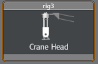
CraneHead
-
Lensfile
Pivot Rotation
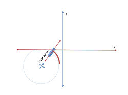
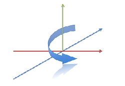
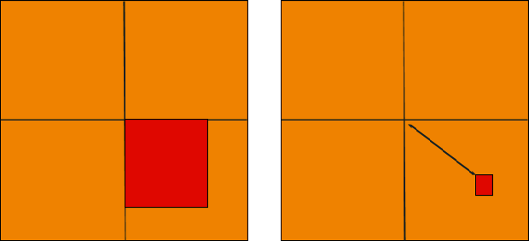
Rotates the coordinate system of a rig around a free definable point in space. The camera Rig is bound to the pivot point in a parent-child relationship.
PivotX, PivotY and PivotZ define the location of where the rotation takes place. Rotation specifies the rotation in degrees around the Y Axis of the pivot point.
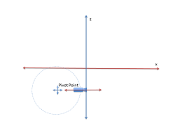
After the rotation, the coordinate system of the Rig is rotated around the Pivot Point. This is useful if, for example, a rail tracker needs to be adjusted in angle and offset to a studio coordinate system.
Location Pivot Rotation
The location pivot rotation rig is similar to the Pivot Rotation. The difference is that this rig takes the pivot point coordinates from the child camera’s position offset, which is attached to the camera position. This rig accepts only a rotation angle, as the position is taken from the child position offsets.
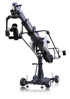
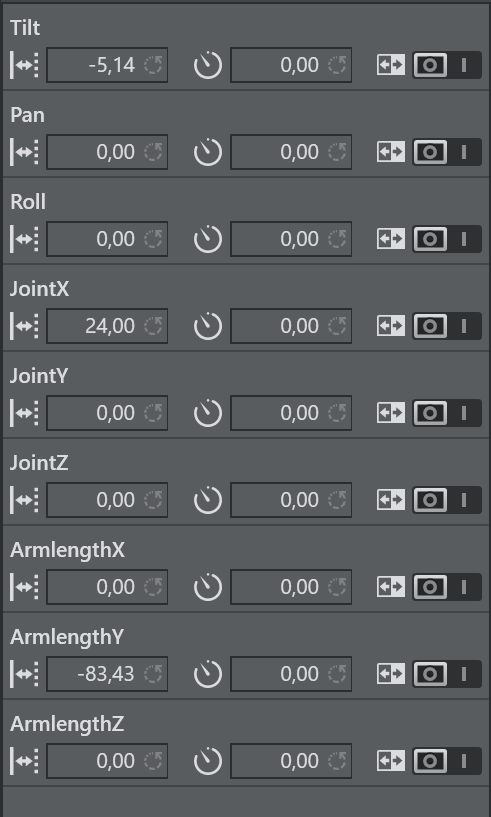
Arm Rig
The Arm rig is mainly used for Spidercam setup, or anywhere a mounted arm follows a rotation axis. The rig does not include any head length or angle adjustments to the next child. All rotations that go into the Tilt, Pan and Roll axis are given to the next sibling. It is possible to set JointX, JointY and JointZ values to adjust mounting offsets between the position giving element and the arm.
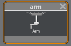
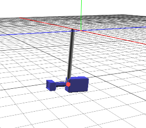
The arm length coordinates define the direction and length of the arm.
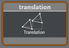
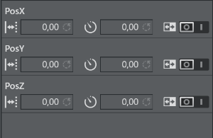
Translation
The Translation rig is mostly used as parent rig to an Arm or CraneArm Rig. It lets you modify the position of all child rigs. PosX, PosY and PosZ can be used to track the position. It is a usual element in a Spidercam setup.
Crane Arm
The Crane Arm rig is used to represent a crane arm. The difference from the normal Arm Rig is that the direction fields define a normalized direction of the arm, and the length is defined by the ArmLength field. In the arm rig, the Length parameters can be separated by axis.
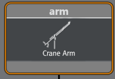
You can set JointX, JointY and JointZ values to adjust mounting offsets between the position giving element and the arm.
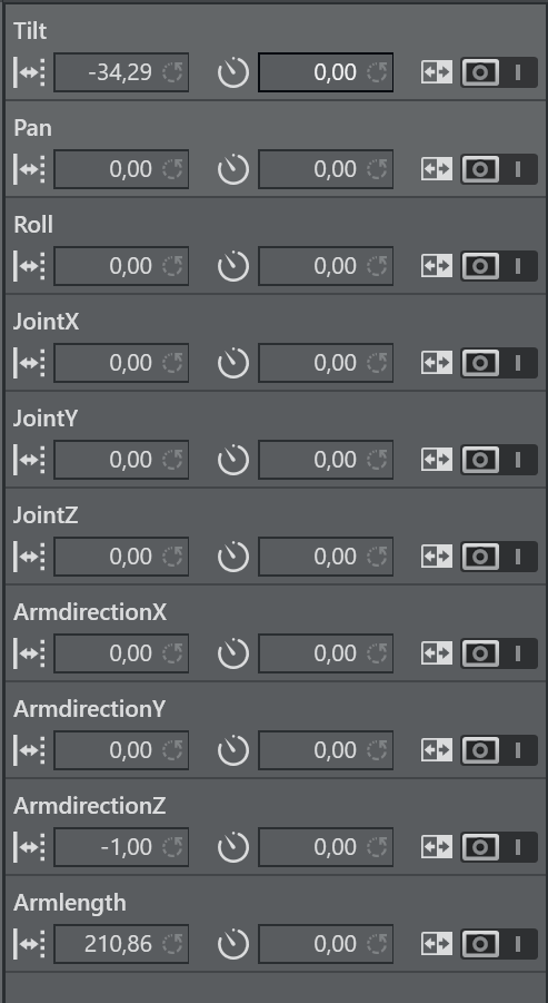
ArmdirectionX, ArmdirectionY and ArmdirectionZ are normalized to 1 and define the initial direction of the Arm. Usually, ArmdirectionZ is set to -1.
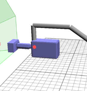
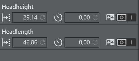
Crane Head
A Crane Head represents a perpendicular element, which can be attached to a crane arm, or to a simple arm. The Headlength defines the horizontal length in -Z direction after the perpendicular element. The Headheight defines the Height in -Y direction after the perpendicular element.
Lens File
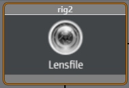
The Lens File rig must always be the first in a rig hierarchy. It is able to select one of the lens files, which must be located in the Lensfile folder in the Tracking Hub configuration folder in %ProgramData%. Once in the hierarchy, the lens file interprets the incoming raw zoom and raw focus values and sends FieldOfView, K1, K2, CenterShift and NodalPoint to the engine. The camera service object must be targeted to the lens file rig.
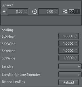
The only trackable parameter in the rig is the lensext parameter. In some protocols, such as FreeD, the lens extender is tracked. The value of lensext can be 0 or 1. If it is 0, the first lens file is used. If set to 1, the second lens file is used. The scaling values define a scale factor for the field of view with respect to the actual zoom value. ScYNear and ScXNear are the scaling factor when the lens is completely zoomed in. ScYWide and ScXWide define the scaling factor when the lens is completely wide. Between Wide and Near, the values are interpolated. If you do any changes inside the lens file or add some new, you must press Reload to make them available in your configuration.
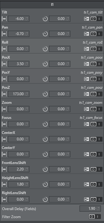
Camera Rig
The Camera Rig represents the simplest camera known in the Tracking Hub. It holds the rotation and position parameters of a real camera in the studio. Zoom and Focus (in raw format coming from an encoder) and the Front, Height and Right lens shifts which are coming from the mount of the camera.
CameraFD Rig
The CameraFD Rig is similar to the standard camera, but with special developments for the Spidercam fielddolly (FD) and a changed rotation order ( X Z Y ).
Position and Rotation
Tilt, Pan and Roll defining the rotation of the camera around the X,Y and Z Axis. PosX, PosY and PosZ define the position of the camera in space. Each of these values might be tracked. In the case of a Pan/Tilt camera head which does not provide position information, the position can be adjusted in the offset values.
Zoom and Focus
Zoom and Focus come from the Lens encoders (whether internal or external). In the system and in Viz Engine, these values are always normalized and go from 0 to 1. Therefore, it is most important that the Lens Ranges are calibrated correctly in the tracking system.
Center Shift
Whenever you mount a lens to a camera body, the connection is never 100% the same every time; hence, there is always an offset between the camera body and the lens which shifts the angle of the light onto to charge-coupled device (CCD). In the Viz Virtual Studio software, this effect is called the Center Shift.
Note that every lens shows its own center shift and can for the most part be ignored as it is much smaller than the center shift caused when mounting the lens to the camera body. The most visible center shift is caused by the actual mounting of the lens and is more and more visible as the mount connection between the camera body and the lens becomes damaged/worn.
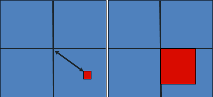
In order to calibrate the center shift, the Camera Rig handles the CenterX and CenterY offsets the following way: Completely zoomed out the full offset is applied and sent to Viz Engine. When zooming in, these values go in the zero direction until they reach absolute zero (completely zoomed in). It is absolutely necessary to calibrate this center-shift to get an acceptable tracking result. Whenever you see a movement of virtual objects when zooming in and out, you need to check if the center shift has changed.
Note: Always check the center shift after mounting your lens to the camera body!
To calibrate the center shift, follow the algorithm below:
-
Reset the CenterX and CenterY values to zero.
-
Look for a corner or easy to identify point in the camera view.
-
Enable the Center Shift Cross in Viz Artist, see Scene Settings > Virtual Studio.
-
Zoom in completely to this point and adjust focus. This is also a good point in time to check the back focus of the camera.
-
Pan and tilt the camera until the corner or point aligns with the Center Shift Cross.
-
Zoom out completely and see that the point slides away from the center.
-
Adjust the CenterX and CenterY values until the corner or point aligns with the Center Shift Cross again.
-
Zoom out completely. If the Center Shift Cross is no longer in the corner or point, repeat from step 5.
Note: Repeat the steps until the Center Shift Cross is on the corner or point at all times. After two or three iterations, this is usually the case.
Mounting Offsets
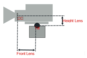
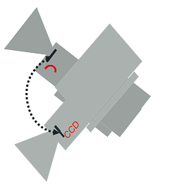
In order to get an acceptable result, we need to know the exact position of the camera’s charge-coupled device (CCD) position. The CCD is (after the optical nodal point) the position of the Viz Engine remote camera. Not every tracking system gives that position. More likely, the position of the last rotation axis on the mechanical head is given, which in most cases is the tilt axis. If the send position is not clear, you need to contact the vendor of the tracking system.
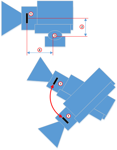
After mounting a camera to a head, there are always offsets between the tracked point and the CCD of the camera. Many cameras have a mark on their body which marks the position of the CCD. If no mark is visible, you can assume that the CCD is 2 cm behind the mounting point of the lens.
In Tracking Hub, we know three mounting offsets. The FrontLensShift, HeightLensShift and the RightLensShift. The following drawings show the Front and Height Lens Shift and how these values change the behavior of the CCD.
Extended Lens Parameters Rig
The Extended Lens Parameters rig holds parameters which are rarely used and delivered by TrackMen and Libero only.
Object Rig
The Object rig is used to position an object in Viz Engine with the use of shared memory and the object service. It can be used to mask out pedestals, which would be in view of other cameras or to track objects with the Motion Analysis tracking system. Pan/Tilt/Roll are the rotation angles of the object and PosX, PosY and PosZ are the position in centimeters (cm). Connected to an Object-Service the coordinates are sent to Viz Engine and can be applied to any objects in the Viz Artist scene tree by a script.
Basic Camera
The Basic Camera rig object has to be attached at the end of every rig structure. The most basic and commonly used parameters required for exact tracking are stored in this rig object. This section shows how the Tracking Hub needs to place the idealized OpenGL point camera to create an approximation of the physical studio camera.
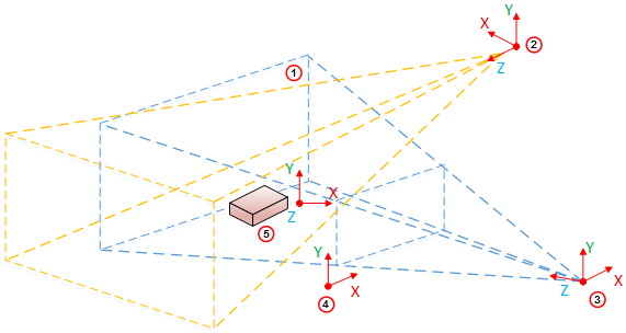
|
Item |
Description |
|
1 |
Clip space |
|
2 |
Light Space |
|
3 |
Camera Space |
|
4 |
Image Space |
|
5 |
Object Space |
By default, the OpenGL camera is a point in space. All transformations (perspective and model view) are linear. It does not matter how much the zoom is increased in the perspective, or how near the camera is to an object in the model view transformation: A straight line in the model space is a straight line in the image projection. When the camera is rotated, it rotates around its position.
Nodal Point
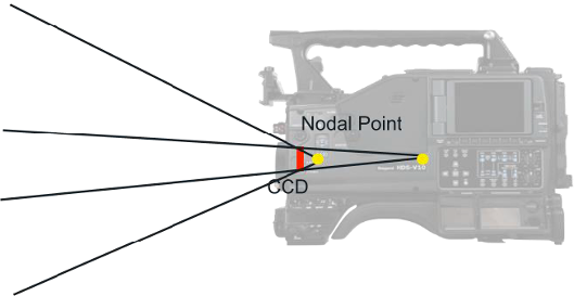
Let us assume the OpenGL camera is placed on the charge-coupled device (CCD) of the camera body. In the image, above, it completely depends on the field of view, where the light rays reflected from an object conjure to a point and create a sharp picture on the CCD. For sports, where the real camera is far away from the observed objects (we assume distances of more than ten meters), there is no influence from the adjusted focus. Therefore, in the image above we only observe the zoom effects on the nodal point of the objects watched.
Zooming in and out, causes the light rays, going through the lens, to conjure on a moving point behind the lens. In our Viz Virtual Studio software, we call this point the Nodal Point, and this point marks the position where we have to place our idealized OpenGL camera. The Nodal Point is defined during lens calibration, which is still happening in the Viz Engine. Therefore it is not an error, if you zoom in and out, and the position of the camera is moving towards and away from the Look-At direction of the camera. This is intended and must be done to provide an accurate result.
Note: Currently the Nodal Point comes from the lens file only.
Center Shift
Whenever one object is mounted to another, the connection is not 100% straight. This is true for camera bodies and lenses as well. There is always an offset angle between the camera body and the lens. Therefore, the light does not come completely straight to the CCD. In the Viz Virtual Studio software this effect is called the Center Shift. Every lens shows its own center shift, which is much smaller than the mount error center shift and can be ignored most of the time. The most visible Center Shift is caused by the mount and becomes more and more visible/evident as the mount connection between the camera body and the lens becomes damaged.
Note: Currently Center Shift can be corrected in the lens file only.
Mounting Offsets
|
Item |
Description |
|
1 |
CCD |
|
2 |
Height Lens Shift |
|
3 |
Tilt Axis |
|
4 |
Front Layer |
Timing
As a prerequisite for a virtual studio, every part of the equipment must be synchronized. This includes the Viz Engines, the tracking systems and the Tracking Hub.
The Tracking Hub can be synchronized in two ways:
-
Using a synchronized Viz Engine as sync source, or
-
A Plura PCL-PCI card.
It is the possible to switch the Tracking Hub to freerun mode. This is not intended for production purposes, rather it is meant for emergencies and experiments. Never under any circumstances use freerun mode for production. Even in freerun mode, the Tracking Hub generates a smooth result, but a change in delay becomes visible periodically. This occurs when the free running Tracking Hub swaps over the field border of a synchronized Viz Engine.
It is possible to run Tracking Hub in low latency mode. This is the case when the overall delay is set to a value below 1 in the rig. If you see missing data packages (indicated by warning displayed on the tracking system) you can increase the delay to values over 1. At that point, Tracking Hub starts to interpolate missing tracking packages. If, from time to time, one data package is missing, a delay value between 1 and 2 is enough to smooth the data. When more than one package is missing (two successive missing packages), the delay must be increased accordingly. Even if this is possible with the Tracking Hub now, we want to achieve as low delay as possible. So if you see missing packages, you need to check the connection to the tracking system. Check if the system is synchronized in a correct way or find out what is causing this wrong behavior.
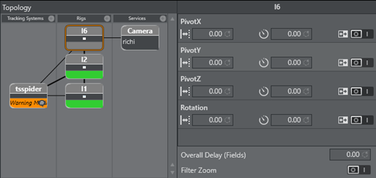
Use the timing monitor in Studio Manager to check the timing behavior of a tracking system.
Delay
The responsible technicians are confronted with delays between the incoming tracking data and the incoming video signals when a virtual studio is set up. We do not handle audio delays here, because audio is, in most cases, handled by the TV station’s audio department.
We handle two different kinds of delays in the virtual studio:
-
Video Delay
-
Tracking Delay
Video Delay
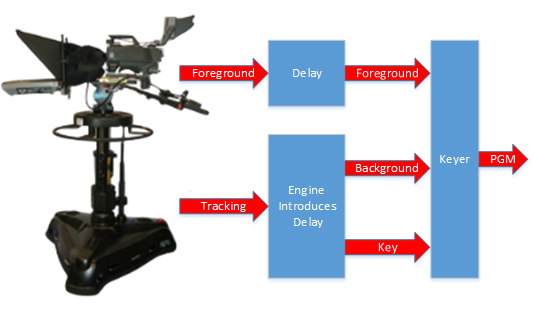
It is assumed that the camera and the tracking system are connected to the same sync signal. When the camera records an image, the tracking system acquires the camera's position, does some calculations and then sends this data to the Tracking Hub. One field later, Tracking Hub sends this tracking information to Viz Engine. Unfortunately, Viz Engine needs time to first render the image and additional time to output this image through the video card to its output. Normally, this process needs about two or three frames, depending on the video hardware used.
If we route the image from the camera directly to the keyer, the video is presented before the rendered image from Viz Engine. Therefore, delaying the video for a specific time is required to achieve a close match between the real image (i.e. the foreground in the virtual set) and the rendered image (i.e. the background in the virtual set). To apply this video delay, it is (or was) required to introduce a delay line which delays the video for a specific amount of frames.
Note: In interlaced modes, video can not be delayed for fields. Video delays can only be applied on a frame base.
Modern Keyers, such as the Ultimatte 11 or the Saphire 3 have built in delay lines. An extra delay line must be installed when using older hardware.
Tracking Delay
![]()
![]()
After reading the last section about Video Delay, you may have the impression that tracking systems and cameras sample the position or record the image exact at the flank of the sync signal (blackburst). This is not the case. Depending on the exposure time, iris and gain we do not know when the camera is recording the image. We only know for certain that the camera sends the image out at the next sync. But we don’t know at what time during the field the image was recorded. Still worse, if you have a long exposure time (for example, two milliseconds) where is the point in time, the image was recorded?
The same problem occurs with tracking systems. Mechanical tracking systems are always near the sync flank, but they are never exactly at the flank. They always need a few milliseconds to read all the encoders and calculate the position from them. Using optical tracking systems compounds these problems. At what point in time are the cameras shooting the targets? We do not know. The only thing we know for certain is that there is always a fraction of a field delay between the tracking data and the video data, even when the video delay is set as accurately as possible.
From the last chapter we know, that video delay can only be set in whole values of frames. How do we set the fraction of a field?
Note: When the delay differs 0.1 field from the video, it is visible to the eye!
The only way to solve this problem is to interpolate using the tracking data received by Tracking Hub. There is an Overall delay setting in the Studio Manager Rig control that can be used to interpolate the tracking data in fractions of fields. In addition, every axis can have its own delay bias. This is useful, when mixing different tracking systems. When the overall delay is set to 0.5, the Tracking Hub interpolates a half field back in time.
But what can you do if the delay must be set to -0.5 to achieve a good result? This is not possible. We cannot attempt to extrapolate the data, because this probably results in ugly jumps. In this case, the only solution is to increase the video delay.