
Viz Multiplay User Guide
Version 2.5 | Published February 18, 2019 ©
Using Datapath Fx4 display controller
When considering how to distribute the pixels from the Viz Engine output renderer to physical devices, there are numerous solutions. The two main solutions are using nVidia Mosaic and using the Datapath Fx4 MultiDisplay Controller. This section describes the usage of the Datapath device.
Viz Multiplay integrates with the Datapath Fx4 MultiDisplay Controller:
Image is not available
In principle - the Viz Engine draws its output on a renderer surface with a resolution covering the complete output surface. From the renderer surface, it is possible to grab pixel areas and distribute them through one or more Datapath devices to physical outputs (screens). The first step of the configuration is to set up the physical mapping from the input signal to the physical screens. This is done with the software provided by Datapath. When this is done - the Datapath configuration file can be imported into Viz Multiplay and act as a backdrop when creating presets (video wall layouts).
In this section, we will go through a typical setup covering the following:
The details of the Datapath setup will not be covered here. Please consult the Datapath Fx4 manual.
Connecting the devices
The Datapath Fx4 device accepts up to 4K input through DisplayPort. There are different ways of utilizing one or more Datapath devices together with a Viz Engine. It is recommended to have one GPU from the nVidia Quadro series. These cards typically have 4 outputs. If the video wall needs more than a 4K resolution, two or more of the outputs from the GPU can be combined with nVidia Mosaic to create for instance an 8K surface. It is also possible to use Loop Through on the Datapath device to distribute the original signal unchanged to other outputs.
The Datapath devices can scale, duplicate or rotate any part of the input surface, so the output wall can have any aspect and resolutions. Rotation is only supported by 90 degrees.
Note:
Needless to say - larger resolutions demands more powerful hardware. Have in mind what kind of content, which formats, how many clip and live channels, and the complexity of the graphics the Viz Engine should handle when scaling the wall to large resolutions.
In our typical setup, we connected two outputs from the GPU to each of the two Datapath devices through DisplayPort. We then connected 4 HD screens to each of the Datapath boxes. To control and configure the Datapath devices, we connected the boxes with USB to a separate PC on the network. We installed the Datapath Wall Designer software on this PC. The setup looked like this:
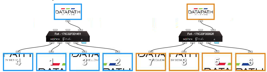
In this setup we use two 4K inputs from the GPU and distribute them to 8 screens.
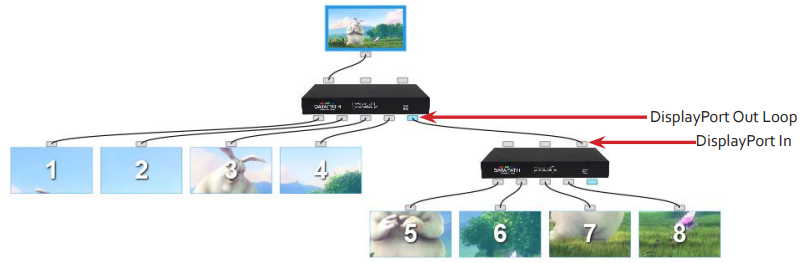
An alternative approach would be to settle for less input resolution and distribute one 4K input to the 8 screens, using Loop-Through. In this way, if the output screens are HD (1920x1080), the HD screens will show scaled-up content from the 4K input. If this is an acceptable resolution on the output - it will give better performance.
Using SYNC
To synchronize the output and input devices, it is vital to use a sync signal. The Fx4 must be genlocked to all external devices. Connect the external sync signal to each of the Datapath devices, to the nVidia GPU and the Matrox video card.
Calculating resolution
If your wall consists of one large surface without any bezel between screens, the input source resolution in the Datapath configuration can be set to match the wall resolution, given that the total resolution is under 4K (3840x2160). If the resolution of the wall is over 4K, and input resolutions need to be stitched together, each of the input resolutions are summed up to a total resolution, which is the resolution reported through nVidia Mosaic to the Viz Engine. This resolution can be seen in the Output Format section in Viz Engine Configuration.
Tip:
Even though the official limit of the DisplayPort input for each Datapath box is 4K/60fps - this is a truth with modifications. The real limitation is the amount of data transmitted over the DisplayPort cable. This is limited by the DisplayPort standard "HBR2" which has a limit of 17.28 Gbit/s. This is enough for 4K/60 with 8bit per color. If the refresh rate is 50, the resolution can be slightly higher than 4K.
The bandwidth can also be affected by the cable length. Please consult the Datapath manual.
Bezels
If the screens connected to a Datapath device has a frame around the active area - the distance between the screens should be encountered in the total input resolution. The distance contains invisible pixels that will be drawn by the Viz Engine renderer, but cut away by the Datapath box. There are two ways of taking bezels into account:
-
Set the input resolution to a total of 4K or whatever the Viz Engine should output. Then, to count for the distance disappearing between the screens, calculate how many pixels are left for each screen. Example: Input resolution is 4K (3840x2160). Output screens are HD (1920x1080). Now, there aren't enough pixels in the input resolution to fill each screen with full HD and cover the distance between the screens. You need to calculate how many pixels you have per cm in total and reduce the capture area available for the screens. The Datapath box will scale up the content to fill the screens. This method is hard to calculate and get correctly configured.
-
The easier way: Set the input resolution to higher than the total resolution of the screens to cover for the lost pixels. Calculate how many pixels you need to add to the input resolution (horizontal and vertical) to let the screens have their content in full resolution (1920x1080 for instance), and add the amount of pixels needed to cover the gap between the screens.
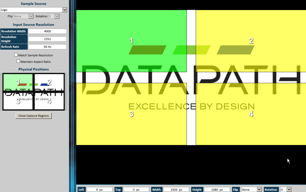
In our setup, we used method number 2. We found that we had to add about 170x192 pixels to the total resolution to cover for the pixels between the screens. So the total input resolution was 4000x2352. As we run in PAL (50Hz), we still are under the maximum bandwidth of the DisplayPort capacity. In this way - the capture regions for each screen is 1920x1080, and they are placed in the corners of the total surface:
In our setup, two Datapath devices were connected to 4 screens each. The bezel internally between 2x2 screens is taken care of by the Datapath configuration, as shown above. But there is also a gap between the two blocks of 4 screens, which is outside the Datapath areas. This gap (170 pixels) was taken care of in the nVidia Mosaic configuration. The total resolution for the renderer then became 8170x2352.
Setting up the video wall in Multiplay
In Multiplay, the goal is now to use the Datapath configuration as a backdrop for editing the GFX channel layouts (presets).
Create the video wall
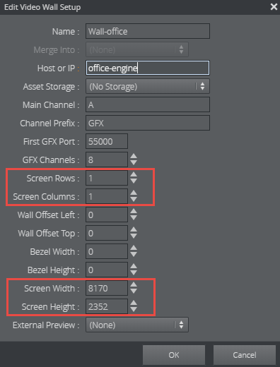
First of all, when creating a new video wall in a profile, we now know that the physical layout of the wall should be determined by the Datapath configuration, and not rows and columns in a nVidia Mosaic setup. We therefore specify that our wall consists of one, big surface (1 row and 1 column) and specify the screen size to match the total resolution of the Viz Engine renderer. In our typical setup, 2 x 4K plus bezel between the screens ended up in a resolution of 8170x2352.
Video Wall Designer
In the Video Wall designer, it is possible to create and edit the Active Areas, which will become snap points for the GFX layout (the presets). But since the visual configuration already is done in the Datapath Wall Designer, we can import this configuration into Multiplay. In Datapath Wall Designer, you need to save the configuration. This becomes a *.wdl file, which consists of an XML structure describing the Datapath setup (inputs and capture areas). If you have more than one Datapath box connected to the computer running the Wall Designer, or on the network, the wdl file contains the combined configuration.
-
In the Video Wall designer, click the Active Areas Editor button:
![]()
In the Active Areas editor mode, the GFX channels are hidden, and only the backdrop is visible. For now, the backdrop is one, empty area.
-
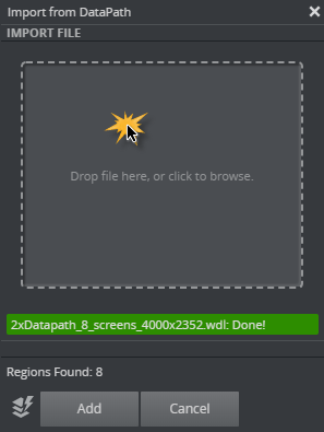
Now you can import the wdl file by clicking the Import button:
![]()
A dialog box then opens. Either click the area in the middle or drag the wdl file into this area. The PC you're running Multiplay on needs to have access to this file, either from a shared disk - or you can copy the file from the Datapath Wall Designer PC to the Multiplay PC first. When the file is read - a green status message will display the file name and a "Done!" message. Under this message, the number of Datapath wall regions (capture areas) is displayed.
-
Click Add to generate the Active Areas in the Video Wall designer.
The next time this operation is done - it is possible to clear the existing Active Areas first, by clicking the following toggle button:
![]()
After importing and possibly editing the Active Areas from the Datapath configuration, the Video Wall designer may look like this:
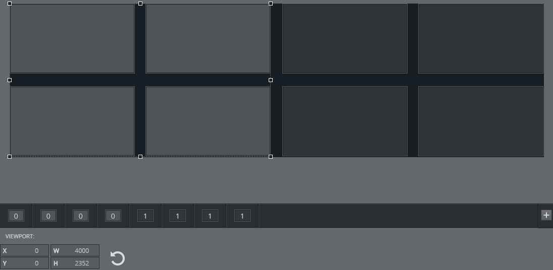
In this case, we have imported 8 regions from 2 Datapath boxes. Each of the Datapath devices is represented as a group of Active Areas. The numbers below the editor (0 and 1) indicate which group each area belongs to.
-
Clicking once on an Active Area will select this area individually.
-
Clicking the next time will select the group this area belongs to.
Tip:
When importing a Datapath configuration containing more than one Datapath device, the groups will initially be placed on top of each other in the editor. The Datapath configuration contains no info on where the outputs of the devices are located relative to each other. In our typical setup, both groups of 4 screens ended up on the left side of the editor. The second group then had to be dragged to the right side of the video wall representation in the editor. In this case, it is useful to enable the "Live" function and the "Fill color" function to ensure that the Active Areas actually match the monitors in the video wall.