
Viz Mosart Administrator Guide
Version 5.6 | Published July 22, 2024 ©
Video Servers
Viz Mosart is capable of controlling video servers from many different manufacturers. Although the end result is the same, each video server type operates in a slightly different way.
It is essential that the correct settings are defined in AV Automation for Viz Mosart to effectively and correctly control your video server. You reach these settings with
-
AVAutomation > Devices > Properties> Video Servers tab.
-
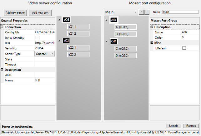
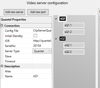
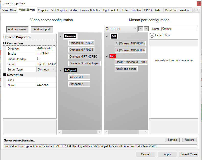
The left side presents details of the physical video server, and any port configurations.
The example above presents a Quantel server, sQ1 (as selected from the Server Type drop-down menu), and one other server (sQ2), which could also be a Quantel server.
Server sQ1 has 2 ports defined, sQ1:1 + sQ1:2.
Server sQ2 has 2 ports defined, sQ2:1 + sQ2:2. -
The right side presents details of the virtual connection within Viz Mosart, with salvo definitions.
This is described in Video Servers.
This rest of this section contains the following topics, presented according to the configuration menu illustrated above, from left to right:
Working with Video Server Configurations
You can add or remove video servers to your Viz Mosart system, and modify the configuration of existing hardware.
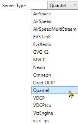
Viz Mosart supports a wide range of video servers. These can be viewed from the Server Type drop-down menu.
Note: Only compatible combinations of Media Administrator and AV Automation drivers can be defined. Please contact Vizrt Support for further details.
-
The Name property links the selected video server to a Media Administrator properties line.
-
For an explanation of the various configuration properties, please refer to the specific video server model, as presented in Video Servers below.
-
After configuration, restart Media Administrator and AV Automation, and ensure that the GUI is connected to the required server.
-
Verify that all indicator lights for the selected video server go green.
Tip: If you do not get green lights, and you see a message similar to this in the Mosart log:
Failed connecting to video server K2:
The source was not found, but some or all event logs could not be searched.
Inaccessible logs: Security.
you can try to start AVAutomation as Administrator. This is a known issue with Grass Valley servers. More info here: http://www.gvgdevelopers.com/concrete/apis/appserver_api/windows/
Video Server Properties
Here are some guidelines for common video servers that Viz Mosart can work with.
Common Settings
Several of the settings are always required, as listed here
-
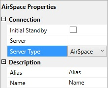
Initial Standby: If selected, the server is forced to start in Standby mode.
-
Server: Defines the hostname or IP address of the video server.
Note: For EVSXedio, a value for Server is not required.
-
Server Type: Name of supported video server. For example, AirSpace, AirSpeed, EVS LinX, Orad OCIP.
-
Alias: Defines the name of the server to display in the Viz Mosart GUI and Timing Display.
-
Name: Internal name of the server, displayed in AV Automation.
The above settings are typical for
AirSpace, AirSpeed, EVS LinX, EVS Xedio, OradOcip video servers.
Some common video server properties are summarized below:
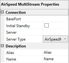
AirSpeed MultiStream
-
BasePort: The first port Viz Mosart uses to communicate with the AirSpeed MultiStream server.
Default: 59451.
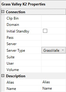
Grass Valley K2
Connection to K2 is initialized with a ping (ICMP) from Mosart to the server to confirm the connection. Then it uses port 3811 to communicate with the K2 server. Both must be open for Mosart to be able to connect.
Manus Admin uses a separate port when it connects: 49171 (a range is OK. Use 49168-49172)
-
Clip Bin: This value, together with that of Volume (see below), defines the default server location of clips to be played. This default location is used only when the location is not provided by other means. (In particular, it is not used when the setting IgnoreBin (in Media Administrator) is true for this server.) The value of Clip Bin should designate a bin in the volume designated by the value of the Volume setting.
-
Domain: The domain as part of the user credentials.
-
Pass: The password as part of the user credentials.
-
Suite: Arbitrary value. However, follow these guidelines:
-
For each K2 server, two or even three unique Suite values must be used:
-
First, the values for Media Administrator and AV Automation must be different.
-
Second, in a redundancy setup with Main and Backup Mosart server, the two values for Media Administrator must be different.
Note: In this constellation, both Main and Backup AV Automation should use the same value, different from the two Media Administrator values.
-
-
-
User: The username as part of the user credentials.
-
Volume: This value, together with that of Clip Bin (see above), defines the default server location of clips to be played. This default location is used only when the location is not provided by other means. (In particular, it is not used when the setting IgnoreBin (in Media Administrator) is true for this server.) The value of Volume should designate a server volume.
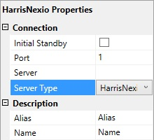
Nexio
-
Port: TCP/IP communication port to the Nexio server.
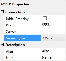
MVCP
-
Port: TCP/IP communication port to the MVCP server.
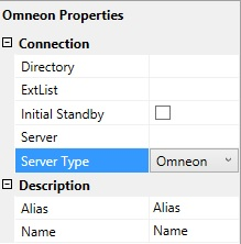
Omneon
-
Directory: Defines the directory where the clips are stored.
-
ExtList: The list of valid file extensions used when listing and querying files on the server. The list is period separated and case sensitive.
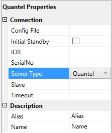
Quantel
-
Config File: The path to the XML configuration file used to define the Viz Mosart - Quantel communication.
-
IOR: The HTTP link including hostname or IP address to the IOR resource on the Quantel ISA manager. Example: http://192.168.100.50:2096/ZoneManager.ior
-
SerialNo: The serial number of the Quantel playout server.
-
Slave: The hostname or IP address of the slave/backup IOR.
-
Timeout: Timeout value for requests from Viz Mosart to ISA manager. If the request exceeds this timeout the server connection is reinitialized. Setting a value here should only be needed for sites experiencing issues with the Quantel connections. Leaving a blank value uses the default timeout.
Recording with Quantel Devices
Quantel requires a duration when preparing a recording. This duration can be set the following ways:
-
As part of a template: Specified using markin and markout properties.
-
As part of a keyboard shortcut: Specified by trailing the ClipName property with [,duration]. Similar to the examples under the general section Controlling Video Servers from Mosart above.
-
As part of template control command: Specified as part of the Parameter property. Again, see the general section above.
TriCaster
The Vizrt TriCaster uses the Video Servers protocol.
Please refer to the procedure below in Video Servers.
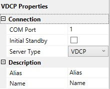
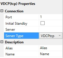
VDCP
-
COM Port: The COM port connected to the VDCP video server.
-
Port: The TCP/IP communication port connected to the VDCP video server.
Viz Engine
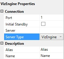
-
Port: The TCP/IP communication port connected to the Viz Engine video server.
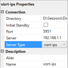
Vizrt-ips
-
Directory: Defines the directory where the clips are stored. The following format can be used: {volume}:/Sessions/{session_name}/Clips/Import
-
Port: The TCP/IP communication port connected to the vizrt-ips video server.
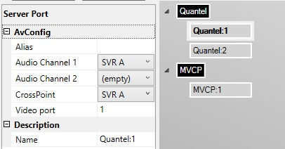
Video Server Port Properties
-
Alias
-
Audio Channel 1: The audio channel 1 for the selected video port.
-
Audio Channel 2: The audio channel 2 for the selected video port.
-
CrossPoint: The video crosspoint for the selected video port.
-
Video port: The actual port name/number on the video server. Please refer to the documentation of your video server for information on how to find these.
For the Server Type vizrt-ips, any recording port must have a 'Video port' of the form recN, where N is a number.
-
Name
Working with Servers and Ports
To Add a Server
-
Click the Add new server button
-
In the Properties pane on the left, select from Server Type and add additional information such as Port and Server host.
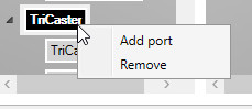
To Remove a Server
-
In the Video Server Configuration tree, right-click a server node and select Remove.
To Add a Port
-
In the Video Server Configuration tree, select a server node
-
Click the Add new port button, or right-click the server node and select Add new port
-
In the property editor on the left, enter the port information.
To Remove a Port
-
In the Video Server Configuration tree, right-click a port node and select Remove.
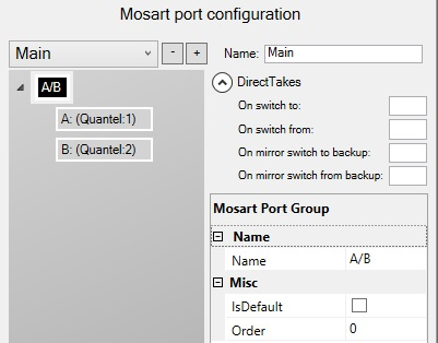
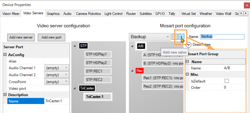
Mosart Port Configurations
Virtual Server Ports
-
Add new salvo: Use the + icon to add another empty virtual video server salvo.
-
Remove a salvo: Use the - icon to remove/delete a virtual video server salvo.
-
Switch between salvos: Use the drop-down menu to select another virtual video server salvo.
If the Media Administrator setting Enable dynamic configuration (see Media Administrator Properties Editor, Configuration) is True, selecting a salvo will also have the effect that Media Administrator connects only to-
those servers that are part of the salvo selected, and
-
those servers which have Static=True in the Media Administrator connection string. (See Media Administrator Properties Editor, Connection Media Search Servers, Video clip Server <n>.)
-
-
Name: Defines the name of the virtual video server salvo.
Direct Takes
-
On switch to: The Recall Nr (see Template Properties) of the direct take template that should be taken when switching to this virtual server salvo.
-
On switch from: The Recall Nr of the direct take template that should be taken when switching from this virtual server salvo.
-
On mirror switch to backup: The Recall Nr of the direct take template that should be taken when switching to a backup server using this virtual server salvo.
-
On mirror switch from backup: The Recall Nr of the direct take template that should be taken when switching from a backup server using this virtual server salvo.
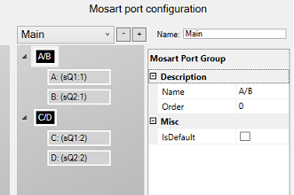
Mosart Port Group
-
Name: The name of the virtual server group. This name is displayed in the server part of the templates.
-
IsDefault: Enable to set the default and preferred video port group for assets residing on multiple systems.
-
Order: See the documentation of the Media Router. If a Media Router is not used, this value can be left to the default 0.
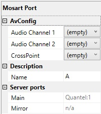
Mosart Port
-
Audio Channel 1: The virtual audio fader 1 for the selected video port. If nothing is selected here, the audio fader from the physical part is used. Default: Empty
-
Audio Channel 2: The virtual audio fader 2 for the selected video port. If nothing is selected here, the audio fader from the physical part is used. Default: Empty
-
CrossPoint: The virtual video crosspoint for the selected video port. If nothing is selected here, the video crosspoint from the physical part is used. Default: Empty
-
Name: The name of the virtual server port, this name is displayed in the server part of the templates.
-
Main: Auto-generated display name of the main video port.
-
Mirror: Auto-generated display name of the mirror video port.
Working with Mosart Port Configurations
The panel on the right-side of the details presented in the Video Servers tab lists any configured ports. This represents a virtual configuration, presented as Viz Mosart port groupings, or salvos. A salvo is a configured constellation of virtual ports (see Video Servers below).
To add a virtual port group
-
Right-click in the Mosart Port Configuration tree (not on a node) and select either:
-
Add virtual ripple group to add a new virtual ripple group. The default ripple group names are A/B, C/D, E/F etc.
-
Add virtual preview group to add a new green virtual preview group node to be used for preview ports. The default preview group name is P.
-
Add virtual recording group to add a new red virtual recording group node to be used for recording ports. The default recording group name is Rec .
-
You can edit or rename the selected group using the Properties Editor on the right.
To remove a virtual port group
You can remove a virtual ripple group, preview group or recording group.
-
In the Mosart Port Configuration tree, right-click any ripple/preview/recording group node and select Remove group <name>.
Alternatively, select a node and press the Delete key. -
When prompted, select Yes to confirm that you want to remove the group from all salvos.
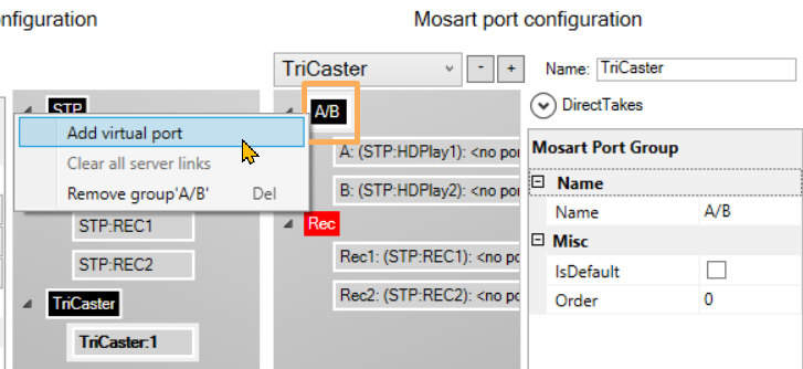
To add a virtual port
-
In the Mosart Port Configuration tree, right-click any group node and select Add virtual port.
If the port was added to a preview group, the added port will be a preview port with default name P. If the port was added to a recording group, the added port will be a recording port with default name Rec.
Note: Do not change the name Rec!
To remove a virtual port
-
In the Mosart Port Configuration tree, right-click any virtual port node and select Remove <name>. Alternatively, select a node and press the Delete key.
-
When prompted, select Yes to confirm that you want to remove the group from all salvos.
Working with Salvos
Salvos are used to switch between server setups. They are used when the operator needs to switch between server parks, for example, when switching to a backup salvo.
Salvos can also be used if different video servers are used in different parts of the show, for instance, sports and news, but you still want to use the same ports.
Note: It is recommended that the default Main and Backup salvos are not renamed.
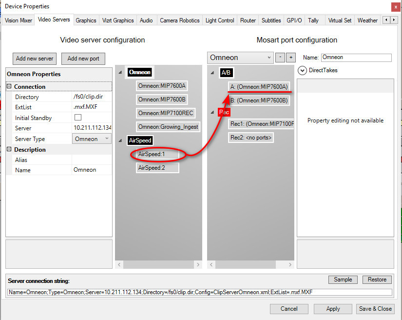
To connect a server port to a virtual port
You can connect a server port to a virtual port:
-
Select the server port (in the left-hand, Video server configuration part) you want to connect, and drag it to the virtual port (in the right-hand Mosart port configuration part) that you use to represent the port in the selected salvo.
Note: If the virtual port is a recording port (in the recording group), the server port to connect must also be a recording port: The physical server must have recording capabilities (and the chosen Server Type must allow for recording).
Mirroring
Mirroring is a redundancy setup (with both servers running at the same time) - an effective method for increasing operational security. Mirroring provides the operator a switch to a server with an identical working state, should there be issues with current server.
This method differs from a Main-Backup setup, which is a failsafe solution (where either main or backup is running, but not both at the same time).
To connect two server ports to one virtual port for mirroring:
-
You need to have two servers already added (in this example, Omneon and AirSpeed Simulator).
-
Select a server port (left side), then drag and drop it onto the virtual port (right side). The right side represents the port of the selected salvo.
The name changes -
Click on the virtual port to verify that the server port from step 2 is now listed as a mirror.
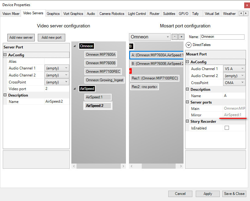
-
Select another server port and drag it to the other virtual port.
-
Click Apply, then Save & Close.
Note: Only two ports can be mirrored.
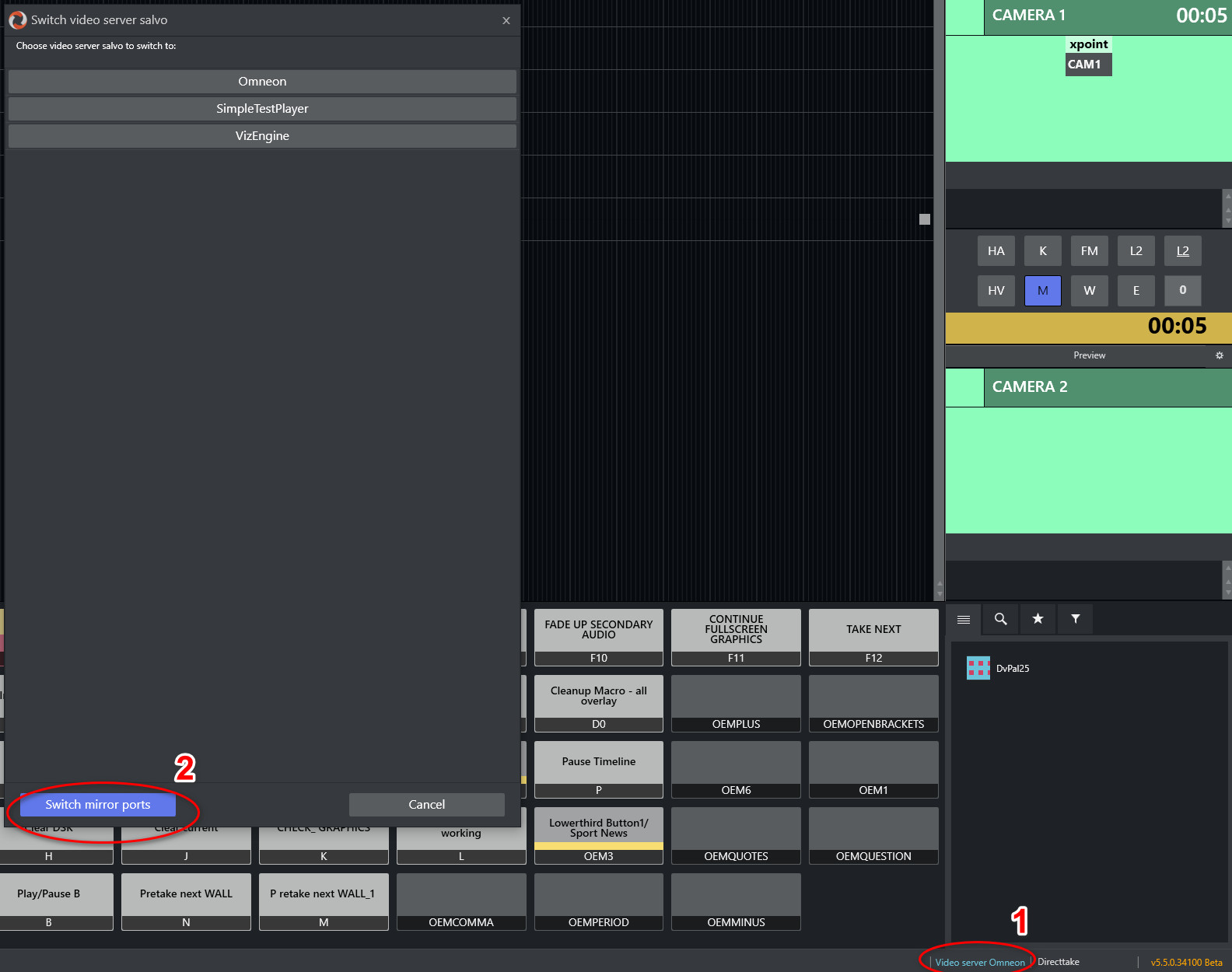
-
Verify that you can now switch between mirrors
-
Either with the newly displayed Mirror button in Av Automation
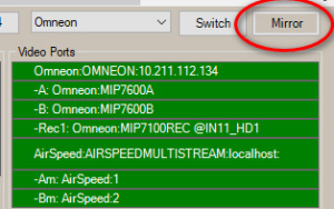
or -
In the Mosart GUI.
-
To add a salvo
Click the Add  button.
To remove a salvo
Click the Delete  button.
To modify a salvo
-
Click the drop down box above the Mosart Port Configuration tree and select the salvo you want to edit.
-
Rename the selected salvo in the Name textbox.
Video Server Recording Setup Example
As an example of a typical video server workflow, this scenario describes how Viz Mosart can control recording of the output from a TriCaster video mixer to a specified video server.
Configuring Viz Mosart
Follow all steps in this section.
To configure AV Automation
-
Navigate to AV Automation > Devices > Properties > Video Servers.
-
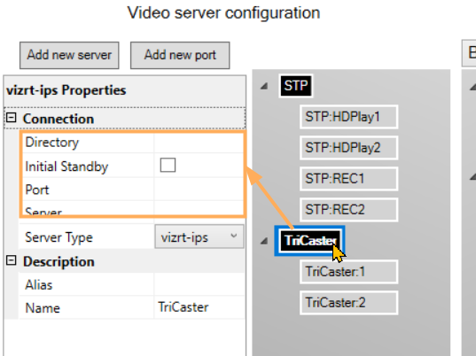
Under Video server configuration on the left side, click Add new server
-
If not in focus, click on the newly created black box, New server.
-
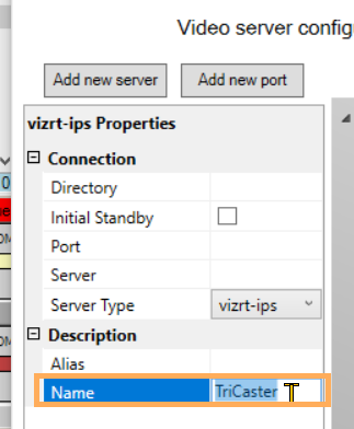
From the Server Type drop-down menu, select vizrt-ips.
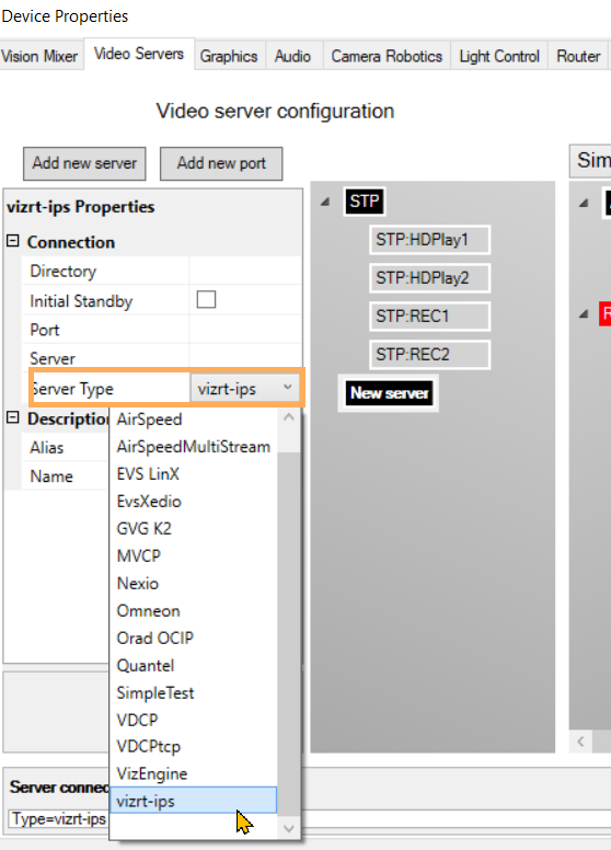
-
Name the server appropriately by filling in Name.
-
Right-click the black box and add a port:
-
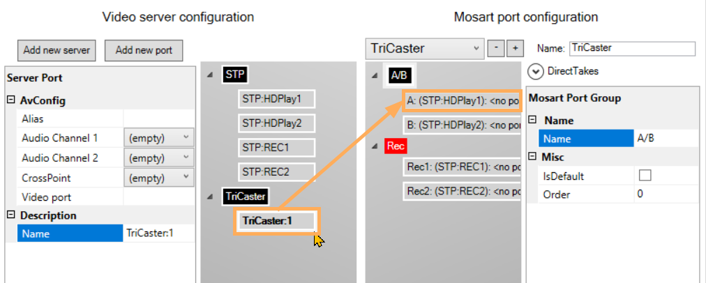
Click the Plus sign on the right under Mosart port configuration.
-
In Name, give this new virtual server an appropriate identity, like TriCaster.
-
Right-click on the black box to add a virtual port.
-
Click on the first Video server configuration (physical) port on the left half and drag-and-drop it to the first virtual one on the right under Mosart port configuration.
-
Repeat with the second port, by repeating steps (9) to (12).
-
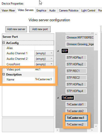
On the TriCaster black box on the left half, add two more ports
-
Fill out the first one with rec1 then press Enter.
-
Fill out the second one with rec2 then press Enter.
-
-
Similarly, fill out the second one with rec2.
-
Now set
-
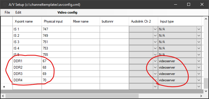
Crosspoint: DDR1 for first port and DDR2 for the second port.
-
Video port: ddr1 for first port and ddr2 for the second port.
-
Name: Any meaningful name.
-
-
This adds a virtual ripple group with 2 virtual ports.
-
Click Apply, then Save & Close.
-
Navigate to AV Automation > Devices > AV Setup > Edit > Video config.
-
Add the crosspoint mapping video server ports as configured on the TriCaster.
The following crosspoints must be mapped:
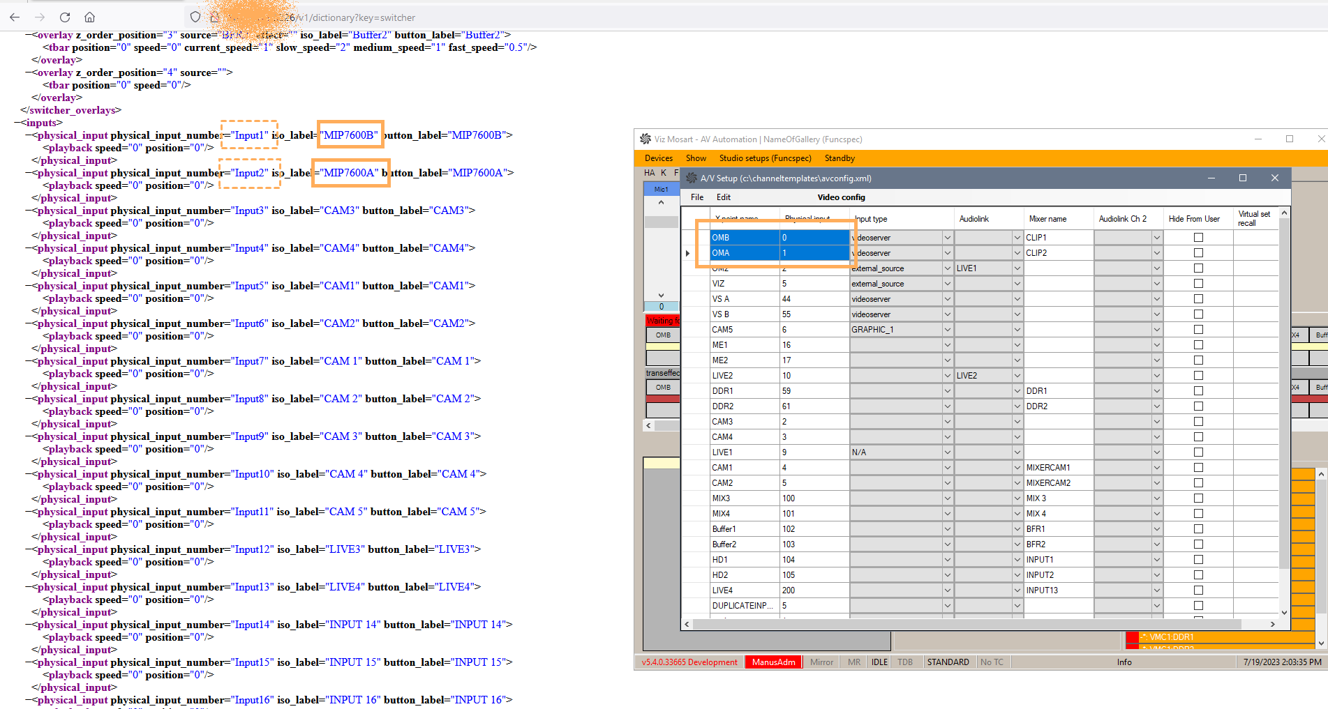
Tip:
-
All (physical) inputs are found by accessing the TriCaster over its REST API:
-
http://<TriCaster_host>/v1/dictionary?key=switcher
-
http://<TriCaster_host>/v1/dictionary?key=tally
-
-
Alternatively, you can access the Physical number by:
-
Opening the Settings for that input:
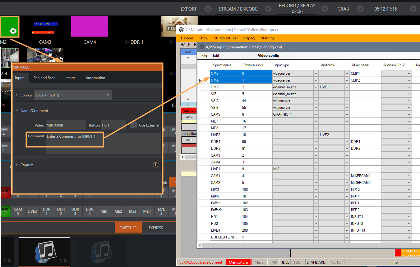
-
Check the number attached to the Input#n text in the Comment.
-
Set the value in Mosart to n-1.
-
-
-
Click on the black box (see below) and configure the following properties for the server:
-
Server: http://<TriCaster_host> as IP number.
-
Directory: {volume}:/Sessions/{session name}/Clips/Import
Note: To find session name:
-
Navigate to the TriCaster DataLink menu:
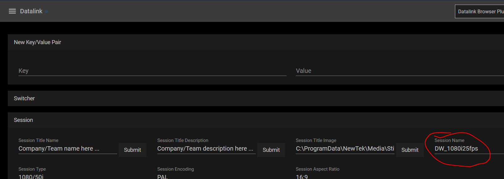
-
The session name is also displayed on the TriCaster home page (hidden menu at the top left corner):
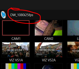
-
-
Extension: let it empty (when Media Service is used, no extension is needed)
Note: The clips id can be given from NRCS without any extension.
-
Name: Any meaningful name.
Make sure Name in the connection string is the same as the one configured in Media Administrator (see To configure Media Administrator below).
-
-
Click Save & Close.
-
Restart AV Automation if needed.