
Viz Engine Administrator Guide
Version 3.12 | Published October 17, 2019 ©
Deprecated Systems
The following servers are deprecated. The information in this section is for historical reference only and is not updated for new hardware.
HP ML350p Gen8
This section describes how to setup a HP ML350p Gen8 machine with the different cards provided by Vizrt:
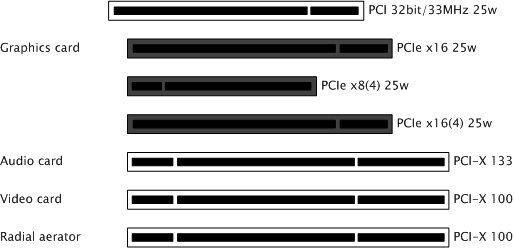
To Setup an HP ML350p Gen8 with a DVS Board
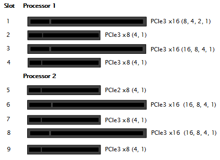
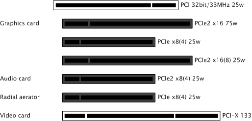
PCI-X, PCI slots, HP ML350p Gen8
IMPORTANT! Before touching any components make sure you use an anti-static wrist strap to prevent electrostatic discharge.
-
Disconnect the power and all other peripherals.
-
Install the video board in slot 1.
-
Install the graphic card in slot 6.
Note: Make sure that the cable connections are correctly mounted and that they stay clear of any supplemental aerators or the aerator of the graphics device.
-
Tidy up all cables and close the computer case.
Note: Placement of cards are the same for both DVS Atomix HDMI (see DVS Centaurus II).
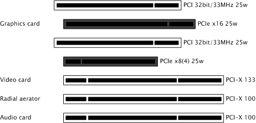
To Setup an HP ML350p Gen8 with a Matrox Board
PCI-X, PCI slots, HP ML350p Gen8
IMPORTANT! Before touching any components make sure you use an anti-static wrist strap to prevent electrostatic discharge.
-
Disconnect the power and all other peripherals.
-
Insert the video board in slot 1.
-
Insert graphic card 1 in slot 6.
-
Insert graphic card 2 in slot 8.
-
Insert the Matrox audio board in slot 3.
-
Insert the radial-aerator in slot 2.
IMPORTANT! A radial-aerator is mandatory as the video board reaches high temperatures during operation.
-
Insert the slot panel (x2) for the X.mio2/44 board in slot 4. Connect it to the X.mio2 board.
-
Tidy up all cables and close the computer’s casing.
-
Start the machine.
Once the machine is powered up, check that the Matrox X.mio board has been correctly installed. Check that the blue OB-light on the (top) backside of the slot panel is set to ON. If the LED is ON the board is correctly supplied with power.
HP DL370
This section describes how to setup a HP DL370 G6 machine with the different cards provided by Vizrt.
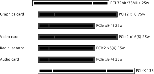
To Setup an HP DL370 G6 with One Graphics Card
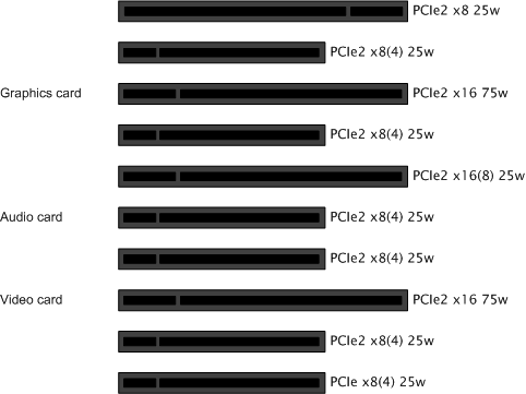
PCI and PCIe slots, HP DL370 G6
IMPORTANT! Before touching any components make sure you use an anti-static wrist strap to prevent electrostatic discharge.
-
Disconnect the power and all other peripherals.
-
Insert the graphics card in PCIe2 slot number 8 from the left.
-
Insert the video board (i.e. Matrox X.mio2) into the PCIe2 slot number 3 from the left.
-
If you have a Matrox board, insert the radial-aerator into the PCIe slot number 2 from the left.
-
A radial-aerator is mandatory as the video board reaches high temperatures during operation.
-
-
Optional: Insert the Matrox into the PCIe2 slot number 5 from the left.
-
Optional: Insert the extra slot panel for the X.mio2/44 board in any of the vacant slots, and connect it to the X.mio2 board.
-
Tidy up all cables and close the computer’s casing.
Note: Matrox DSX.LE cannot be mounted in the DL370 G6
Once the machine is powered up you may verify that the Matrox X.mio board has been correctly installed by looking for the blue OB-light on the (top) backside of the slot panel. A lit light indicates that the board is correctly supplied with power.
To Setup an HP DL370 G6 with Two Graphics Cards
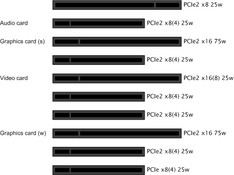
PCI and PCIe slots, HP DL370 G6
IMPORTANT! Before touching any components make sure you use an anti-static wrist strap to prevent electrostatic discharge.
-
Disconnect the power and all other peripherals.
-
Insert the weaker graphics card in PCIe2 slot number 3 from the left.
-
Insert the stronger graphics card in PCIe2 slot number 8 from the left.
-
Insert the video board (i.e. Matrox X.mio2) in the PCIe2 slot number 6 from the left.
-
If you have a Matrox board, insert the radial-aerator into the PCIe slot number 5 from the left.
-
A radial-aerator is mandatory as the video board reaches high temperatures during operation.
-
-
Optional: Insert the Matrox video board into the PCIe2 slot number 9 from the left.
-
Tidy up all cables and close the computer’s casing.
-
Connect the computer’s monitor to the graphics card in slot 3 from the left.
-
Start the machine and in the BIOS (Advanced: Thermal – Full Fan speed) set all fans to run at full speed.
-
Boot and log on to the machine.
-
Install NVIDIA and Video board drivers.
-
Open the NVIDIA Control Panel, and click on System Information in the bottom left corner and check that both graphics cards are installed and run at PCIe x16 speed.
-
If you installed a Matrox board, open Matrox X.info from the system tray and check that the video board runs at PCIe x8 speed.
Note: Matrox DSX.LE cannot be mounted in the DL370 G6
Once the machine is powered up you may verify that the Matrox X.mio board has been correctly installed by looking for the blue OB-light on the (top) backside of the slot panel. A lit light indicates that the board is correctly supplied with power.
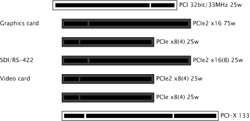
To Setup an HP DL370 G6 with a Capture Card
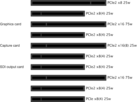
PCI and PCIe slots, HP DL370 G6
IMPORTANT! Before touching any components make sure you use an anti-static wrist strap to prevent electrostatic discharge.
-
Disconnect the power and all other peripherals.
-
Insert the graphics card in PCIe2 slot number 8 from the left.
-
Insert the capture card in PCIe2 slot number 6 from the left.
-
Insert the SDI output board in the PCIe2 slot number 4 from the left.
-
Tidy up all cables and close the computer’s casing.
To Configure the BIOS
-
Start the machine and open the machine’s BIOS system.
-
Go to System Options > Processor Options.
-
Deactivate Hyperthreading. The Matrox X.mio2 board does not function if this setting is enabled.
-
Deactivate Intel Virtualization Technology.
-
Deactivate Intel VT-d2.
Note: Steps 2 and 3 are only needed for VMWare setups
-
Go to Power Management Options > Advanced Power Management Options > PCI Express Generation 2.0 Support.
-
Activate Force PCI-E Generation 2.
-
Save and exit the BIOS.
HP xw8200
This section describes how to setup a HP xw8400 machine with the different cards provided by Vizrt.
To Setup an HP xw8200
PCI, PCIe and PCI-X slots, HP xw8200
IMPORTANT! Before touching any components make sure you use an anti-static wrist strap to prevent electrostatic discharge.
-
Disconnect the power and all other peripherals.
-
Insert the graphics card in the PCIe slot number 2 from the top.
-
Insert the Matrox video board into the PCI-X slot number 4 from the top.
-
Insert a powerful radial-aerator into the PCI-X slot number 6 from the top.
-
Optional: Insert the Matrox video board into the PCI slot number 7 from the top.
Note: A radial-aerator is mandatory as the video board reaches high temperatures during operation.
Once the machine is powered up you may verify that the Matrox X.mio board has been correctly installed by looking for the blue OB-light on the (top) backside of the slot panel. A lit light indicates that the board is correctly supplied with power.
HP xw8400
This section describes how to setup a HP xw8400 machine with the different cards provided by Vizrt.
To Setup an HP xw8400
SATA plug, HP xw8400

IMPORTANT! Before touching any components make sure you use an anti-static wrist strap to prevent electrostatic discharge.
-
Disconnect the power and all other peripherals.
-
Before mounting the video board, the SATA connector originally connected to the SATA port 0 needs to be reconnected to SATA port 1 to make room for the video board.
Note: For an HP xw8400, the X.mio24/6000 video boarInsert the Matrox video board into the PCI-X slot number 6d requires a 64-bit PCI-X slot operating at a minimum of 100 MHz.
-
Insert the graphics card in the PCIe slot number 2 from the top.
-
from the top.
-
Insert a powerful radial-aerator into the PCI-X slot number 7 from the top.
-
Optional: Insert the Matrox video board into the PCI-X slot number 5 from the top.
Note: A radial-aerator is mandatory as the video board reaches high temperatures during operation.
Once the machine is powered up you may verify that the Matrox X.mio board has been correctly installed by looking for the blue OB-light on the (top) backside of the slot panel. A lit light indicates that the board is correctly supplied with power.
HP xw8600
This section describes how to setup a HP xw8600 machine with the different cards provided by Vizrt.
To Setup an HP xw8600 with a DVS Centaurus Board
PCI-X, PCI and AGP slots, HP xw8600
IMPORTANT! Before touching any components make sure you use an anti-static wrist strap to prevent electrostatic discharge.
-
Disconnect the power and all other peripherals.
-
Install the graphics card in slot number 2 from the top.
-
Install the video board in slot number 4 from the top.
-
Install the separate SDI/RS-422 panel in slot number 1 from the top.
-
Make sure that the cable connections are properly mounted and that it stays clear of any supplemental aerators or the aerator of the graphics device.
-
To Setup an HP xw8600 with a X.mio2/X.mio2plus Matrox Board
PCI, PCIe and PCI-X slots, HP xw8600
IMPORTANT! Before touching any components make sure you use an anti-static wrist strap to prevent electrostatic discharge.
-
Disconnect the power and all other peripherals.
-
Insert the graphics card in the PCIe slot number 2 from the top.
-
Insert the Matrox video board in the PCIe slot number 4 from the top.
-
Insert a powerful radial-aerator in the PCIe slot number 5 from the top.
-
Optional: Insert the Matrox video board in the PCI-X slot number 6 from the top.
-
Optional: Insert the extra slot panel for the X.mio2/44 board in any of the vacant slots, and connect it to the X.mio2 board.
Note: A radial-aerator is mandatory as the video board reaches high temperatures during operation.
To Setup an HP xw8600 with a X.mio (first gen) Matrox Board
PCI, PCIe and PCI-X slots, HP xw8600
IMPORTANT! Before touching any components make sure you use an anti-static wrist strap to prevent electrostatic discharge.
-
Disconnect the power and all other peripherals.
-
Insert the graphics card in the PCIe slot number 2 from the top.
-
Insert the Matrox video board into the PCIe slot number 7 from the top.
-
Insert a powerful radial-aerator into the PCIe slot number 6 from the top.
-
Optional: Insert the Matrox video board into the PCI-X slot number 5 from the top.
Note: A radial-aerator is mandatory as the video board reaches high temperatures during operation.
Once the machine is powered up you may verify that the Matrox X.mio board has been correctly installed by looking for the blue OB-light on the (top) backside of the slot panel. A lit light indicates that the board is correctly supplied with power.