
Viz Trio User Guide
Version 3.2 | Published June 29, 2021 ©
Connectivity
The connectivity section is used to configure various interfaces: the Media Object Server (MOS) protocol, Intelligent Interface (IIF), General Purpose Input (GPI), Video Disk Communication Protocol (VDCP), Newstar MCU/AVS, and socket object settings that allow Viz Trio to act as client or a server in a socket connection.
This section covers the following topics:
MOS
To view the MOS configuration settings, click Connectivity > MOS in the Trio Configuration.
MOS Newsroom Integration
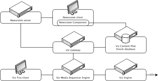
A Viz Gateway (MOS) connection lets Viz Trio monitor playlists (see Playlist Modes) from any Newsroom Computer System (NCS) that supports the Media Object Server (MOS) protocol.
NCSs that support the MOS protocol can deliver newsroom playlists to Viz Trio through the Viz Gateway and Viz Pilot’s database; hence, a MOS integration requires a Viz Gateway, an Oracle database and Viz Pilot’s Newsroom Component.
To establish a MOS connection, the NCS and Viz Gateway must be pre-configured with an NCS and MOS ID. These ID’s are set in the newsroom system.
Note: Most newsroom systems support the MOS protocol and/or Intelligent Interface (IIF) protocols (for example, Avid iNEWS ControlAir).
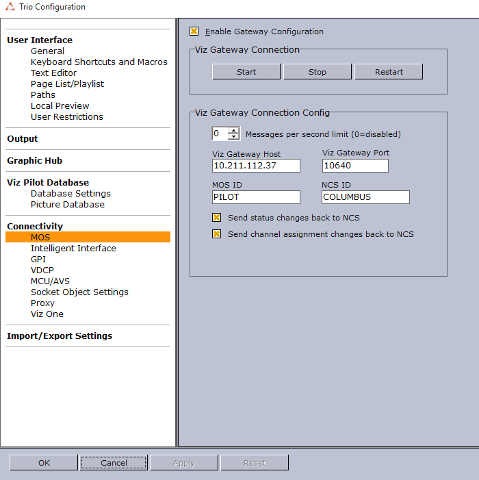
Viz Gateway, MOS Configuration Settings
-
Enable Gateway Configuration: When selected, enables the user to configure the Viz Gateway connection. When enabled, an icon is also visible in the Status Bar.
-
Viz Gateway Connection: The controls in the Viz Gateway Connection section allows a start, stop, and restart action to be performed on a Viz Gateway connection.
-
Start: Starts the Viz Gateway connection.
-
Stop: Stops the Viz Gateway connection.
-
Restart: Restarts the Viz Gateway connection.
-
-
Viz Gateway Connection Config: Define Viz Gateway connection settings.
-
Messages per second limit: Sets how many messages per second that should be sent from Viz Gateway to the NCS. This is done to prevent flooding of the NCS. 0 disables the message throttling.
-
Viz Gateway Host: IP address of the Viz Gateway host.
-
Viz Gateway Port: Connection port for the Viz Gateway.
-
MOS ID: Enter the ID of the connecting MOS device.
-
NCS ID: Specify the ID of the newsroom control system.
-
-
Send status changes back to NCS: Sends new status changes to the NCS.
-
Send channel assignment changes back to NCS: If enabled, will instruct the Media Sequencer to update channel assignments back to the Newsroom system. Hence the next time the MOS playlist gets updated the changed channel assignment stays at the changed element in Trio and is not overwritten by the previous channel value.
The Database Settings for the Viz Pilot Database on the Media Sequencer must be established for the Viz Gateway integration to work.
Note: MOS and NCS ID are not needed for Viz Gateway versions 2 and newer.
Configuring a Viz Gateway Connection
-
Click the Config button to open the Configuration Window.
-
Select the MOS section found under the Connectivity category, and enter Viz Gateway’s IP address and port number (default port is 10640).
-
Click Apply to save the settings to the Media Sequencer.
-
Close the Configuration Window and check that Viz Trio’s status bar shows a green status indicator for Viz Gateway (G).
-
Click the Change Show button, and select the Playlists tab to test that Playlist Modes are available.
IMPORTANT! It is required that Viz Trio sets the NCS and MOS IDs when connected to Viz Gateway versions prior to 2.0.
Intelligent Interface
To view the Intelligent Interface configuration settings, click Connectivity > Intelligent Interface in the Trio Configuration.
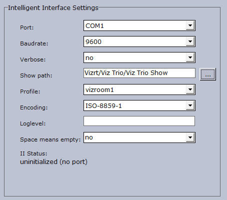
The intelligent interface (IIF) configuration is used to set the parameters the automation system uses to connect to the Media Sequencer over the intelligent interface protocol. Further it defines the Viz Pilot playlist or Viz Trio show the automation system can control and on which output profile.
The Media Sequencer listens to a communications port and acts as the Character Generator (CG) device side of the intelligent interface. The Media Sequencer expects the other side of the communications port to be connected to a newsroom system or similar system that knows how to talk one of the supported dialects of intelligent interface.
The Media Sequencer has two primary tasks:
-
Receive callup data from a newsroom system and store it in the schedule.
-
Trigger actions based on simulated keyboard commands it receives.
Properties and Parameters
-
Port: Sets the serial communications port to be used.
-
Baudrate: Sets the appropriate baud rate for the connection.
-
Verbose: Makes the messages from the Intelligent Interface driver get displayed in the Media Sequencer console. This feature is useful when setting up the system.
-
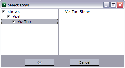
Show path: Sets the path of the playlist or show.
Select Show: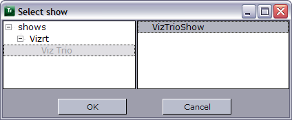
-
Profile: Sets the appropriate profile to be used.
-
Encoding: Sets the appropriate font encoding for the connection.
-
Loglevel: Sets the Media Sequencer Logging for the Media Sequencer.
-
Space means empty: If set to Yes, the graphics template’s default text (when creating an element) is replaced with a space. If set to No, the graphics element will show the default text unless it is manually changed and saved with no text.
General Purpose Input (GPI)
To view the GPI configuration settings, click Connectivity > GPI in the Trio Configuration.
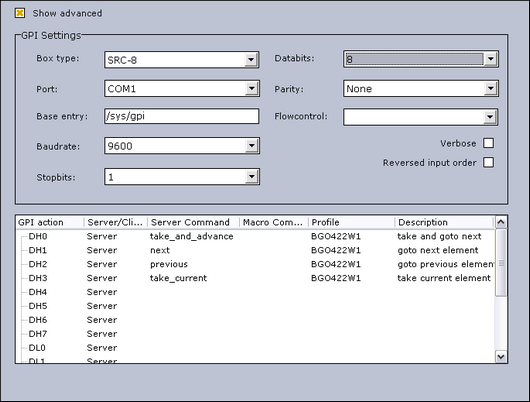
The GPI settings allows the Media Sequencer to be configured to handle GPI commands. The commands can be handled by the Media Sequencer itself (Server Command) or forwarded to the Viz Trio client (Macro Command).
Both server and client side commands are profile specific (see Output), meaning that the profile determines which Viz Trio client and potentially which Viz Engine(s) should execute a client and/or server command. It is therefore very important to assign the correct profile for each GPI action as they refer to unique profiles configured per client.
For example; A Viz Trio client has its own profile with two Viz Engines (program and preview) and receives a client command from a GPI on the Media Sequencer. The command executes some logic on the Viz Trio client that issues commands to the program renderer. If the correct profile is not set, such commands might end up on the wrong Viz Trio client and potentially on the wrong program renderer. The same would happen if the GPI action was defined as a server command; however, it would then trigger commands from the Media Sequencer to the Viz directly and not through the Viz Trio client.
-
Show advanced: Displays all the settings in the GPI Settings frame.
-
Box Type: Select the type of GPI box that is being configured. The Box Type can be set to SRC-8, SRC-8 III or SeaLevel.
-
Port: Sets the port that the GPI box is connected to. The Port can be set to COM1-COM17, or None.
-
Base Entry: This is the node in the Media Sequencer’s data structure where the systems look for the GPI actions. The base entry is by default set to /sys/gpi.
-
Baudrate: Sets the maximum rate of bits per second (bps) that you want data to be transmitted through this port. The Baud rate can be set to 110-921600. It is recommended to use the highest rate that is supported by the computer or device that is being used.
-
Stopbits: Sets the interval (bps) for when characters should be transmitted. Stop bits can be set to 1, 1.5, or 2.
-
Databits: Sets the number of data bits that should be used for each transmitted and received character. The communicating computer or device must have the same setting. The number of data bits can be set to 5, 6, 7 or 8.
-
Parity: Changes the type of error checking that is used for the selected port. The communicating computer or device must have the same setting. The parity can be set to:
-
Even: A parity bit may be added to make the number of 1's in the data bits even. This will enable error checking.
-
Odd: A parity bit may be added to make the number of 1's in the data bits odd. This will enable error checking.
-
None: No parity bit will be added to the data bits sent from this port. This will disable error checking.
-
Mark: A parity bit set to 0 will be added.
-
Space: A parity bit set to 1 will be added.
-
-
Flowcontrol: Changes how the flow of data is controlled. The flow control can be set to:
-
None: No control of data flow.
-
XonXoff: Standard method of controlling the flow of data between two modems. XonXoff flow control is sometimes referred to as software handshaking
-
Hardware: Standard method of controlling the flow of data between a computer and a serial device. Hardware flow control is sometimes referred to as hardware handshaking.
-
-
Verbose: If enabled, the Media Sequencer’s GPI handler outputs log information. This information is useful for debugging.
-
Reversed Input Order: Note that this check box is only available if Box Type is set to SRC-8. If enabled, the signal line that originally triggered GPI action DL0/DH0 will now trigger GPI action DL7/DH7, the signal line that originally triggered GPI action DL1/DH1 will now trigger GPI action DL6/DH6, and so on.
-
GPI action: Shows a list of the available GPI actions.
Commands and actions list: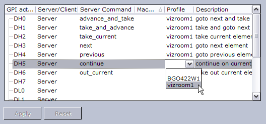
-
Server/Client: Shows a drop-down list box in every row, where the selected GPI action should apply to either the Media Sequencer (Server option) or the local Viz Trio client (Client option).
Note: The server and client actions are reciprocally exclusive.
-
Server Command: Shows a drop-down list box in every row, where the action to be performed on this GPI line can be selected. Server commands are GPI actions that apply to the Media Sequencer. When right-clicking an item in a Create Playlist or Playlist Modes, a context menu opens. In this menu, select Set External Cursor. A red arrow appears next to the selected element in the playlist, which indicates that this is the current GPI cursor. The server commands can be set to:
-
advance_and_take: The cursor shifts to the next element in the playlist, and then runs the Start operation.
-
take_and_advance: Runs the Start operation on the current element, and then shifts to the next element in the playlist.
-
take_current: Runs the Start operation on the current element (the element with the cursor).
-
next: Shifts to the next element in the playlist.
-
previous: Shifts to the previous element in the playlist.
-
continue: Runs the Continue operation on the current element.
-
out_current: Runs the Take Out operation on the current element.
-
-
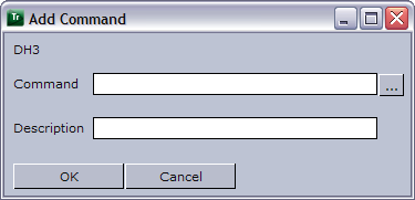
Macro Command: Macro commands are silent GPI actions. Clicking the ellipsis (...) button opens the Add Command window.
-
Profile: Sets the profile to be used for the GPI action. This profile must match the profile set for the playlist that is to be triggered by the GPI actions. The drop-down list shows the profiles configured on the Media Sequencer.
-
Description: Shows the description of the GPI action, as it was specified in the Add Command window.
Assigning a Server Command
-
Select a GPI action, and select Server in the Server/Client column.
-
Select a Server Command.
-
Select a Profile.
-
Click Apply.
Assigning a Client Command
-
Select a GPI action, and select Client in the Server/Client column.
-
Select or create a Macro Command.
-
Select a Profile.
-
Click Apply.
Adding a Macro Command
-
Select the Macro Command column, and click the small ellipse (...) button to open the Add Command dialog box.
-
Enter the command in the Command text field, or alternatively click the ellipse (...) button to open the Predefined Functions window.
Video Disk Communication Protocol (VDCP)
To view the VDCP configuration settings, click Connectivity > VDCP in the Trio Configuration.
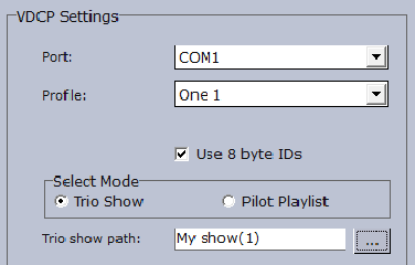
The Video Disk Control Protocol (VDCP) configuration allows a VDCP connection for Media Sequencer to be established in order to externally control a Viz Pilot playlist or Viz Trio show.
With VDCP the Media Sequencer acts like a server that controls the graphics through the VDCP protocol. It sets up a serial connection, and on the other end of the connection typically a video controller is placed. Over this connection VDCP commands are sent, and in this way the video controller is able to control a playlist/show.
The configuration of the Media Sequencer is twofold. There are the general VDCP settings, and there is the configuration for which playlist to control.
The VDCP protocol defines recommended serial settings, but if you for some reason need to use different settings please refer to the Media Sequencer manual’s VDCP section, and in particular the section on "Electrical and Mechanical Specifications", for information on how to configure this.
-
Port: Select the appropriate COM port for the communication.
-
Profile: Select the profile to use.
-
Use 8 byte IDs: Allow the use of 8 character IDs for VDCP protocol.
-
Select Mode: Select a Viz Trio show or a Viz Pilot playlist path mode.
-
Trio path / Pilot playlist: Sets the base directory for the VDCP integration. Video clips will be placed here.
MCU/AVS
To view the MCU/AVS configuration settings, click Connectivity > MCU/AVS in the Trio Configuration.
MCU/AVS Configuration Settings
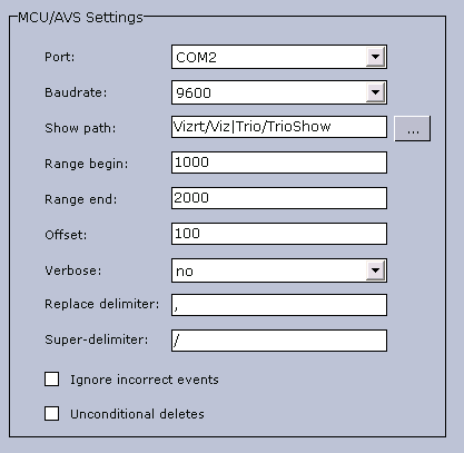
This configuration is primarily used for configuring settings for a Newstar (News*) newsroom system connection.
-
Port: Select the appropriate Com port for the communication.
-
Baudrate: Select the appropriate baud rate.
-
Show path: Base directory for the MCU/AVS integration. Newsroom stories will be placed here.
-
Range begin and Range end: Pages received from the newsroom system will be numbered within this range.
-
Example: If Range Begin is 1000 and Range End is 5000 and Offset is 100. Then Callup pages in story 1 will be numbered 1000, 1001, 1002, and so on. Callup pages in story 2 will be numbered 1100, 1101, 1102, and so on.
-
-
Offset: Sets the offset value that will be used to separate pages from different stores.
-
Verbose: Enables notification messages from the MCU/AVS driver. The messages will show on the Media Sequencer console. This feature is useful when setting up the system.
-
Replace delimiter: Replaces a character with the super-delimiter. For example if set to ‘|’. slashes ‘/’ can be put into tab-fields by entering ‘|’.
-
Super-delimiter: Delimiter used in News* to separate tab-fields. Standard value is ‘/’.
-
Ignore incorrect events: Incomplete scripts from News* will send invalid protocol data. Typically template specifications and supers could be missing. If this option is set to "Yes", then the system accepts incomplete/incorrect story descriptions. Should be set to "Yes" in most cases.
-
Unconditional deletes: Removed in version 1.10. On older versions of Viz Trio, this option should be enabled. This means that a transfer of messages from Newstar starts with deleting existing messages within the specified range. To maintain a proper state handling this method must be used.
Socket Object Settings
To view the Socket Object configuration settings, click Connectivity > Socket Object Settings in the Trio Configuration.
Socket Object Configuration Settings
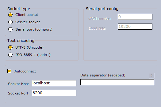
The Socket Object Settings section allow socket connections to be defined for the Viz Trio client. It can either act as client or a server in a socket connection. A serial port connection which uses the same command set can also be set up.
-
Socket type:
-
Client socket: When Viz Trio is set up to be a client socket it will connect to the specified server socket. Specify a host name and a port for the machine that runs the server socket.
-
Server socket: When Viz Trio is set up to be a server socket it will wait for a client socket connection. Specify the port it should listen on.
-
Serial port (Com port): The serial port connections work in principle as a socket connection, but instead of using TCP/IP it uses a null modem cable. The command-set is the same.
-
-
Text encoding: Select a text encoding for the connection.
-
Serial port config: If a serial port connection is to be set up the COM port number and the data baud rate must be specified here.
-
Autoconnect: With this option set, a server socket or a serial port connection will be open/active at all times, but a client socket will first be active when data is sent. If this option is not checked, a "connect_socket" command must be sent before sending the data.
-
Socket Host- The socket server’s host name must be set here if the Viz Trio client is to function as a client socket.
-
Socket Port: For client and server socket a port number must be specified here.
-
Data separator (escaped)- Specifies a data separator for incoming data.
-
Receiving data separator will trigger the OnSocketDataReceived event in Scripts. If unprintable ASCII characters are used as data separators, special character sequences called "escape codes" are needed. All escape codes start with a backslash. For details, see Escape Sequences.
-
When the socket object receives the data separator, the OnSocketDataReceived event is triggered, and the data received since the last separator is issued (not including the separator itself). If Data separator has no value, the OnSocketDataReceived is called continuously as long as data is received.
-
Proxy
To view the Proxy configuration settings, click Connectivity > Proxy in the Trio Configuration.
Proxy Configuration Settings
The proxy function is mostly relevant when Viz Trio and Viz Engine are set up with a direct network link to be controlled by an external control application. A dedicated network card on the Viz Trio client together with a crossed network cable directly to Viz is the normal way to make such a link.
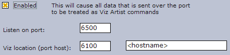
All data sent over the configured listener port will be treated as Viz commands and forwarded by the Viz Trio client to Viz. With the proxy function enabled, the data sent over the configured listener port will be treated as Viz commands by the Viz Trio client. Viz Trio does this by acting as a proxy transmitting commands back and forth between Viz and the external control application.
-
Enabled: Enables the proxy feature.
-
Listen on port: Sets the listener port for Viz Trio that the sender will use.
-
Viz location (port host): Sets the listener port for Viz Engine and the hostname (default is 6100 and localhost).
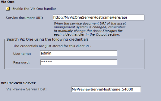
Viz One Configuration
To view the Viz One connectivity settings, click Connectivity > Media Engine in the Trio Configuration.
Viz One Connectivity Settings
The Media Sequencer’s communication with Viz One is related to all Media Sequencer show and playlist elements that contain Viz One elements residing on the Viz One that are initialized for playout.
-
Enable the Viz One handler: If selected, enables the Viz One handler.
-
Service document URI: Defines the Viz One instance to use.
Note: When the service document URI of the Viz One is changed, remember to manually change the Viz One storages for each video handler in the Output section of the configuration. A Viz One storage points to a Viz Engine where the Viz One files are sent for playout. For more information, see To add a video device.
It's possible to define the Viz One server instance based on either an IP address or hostname. It is recommended to use hostname. Host comparisons in the system are generally done by string comparison, not by lookup. This is why either IP or hostname must be selected. This also means that you should not mix hostnames and fully qualified domain names; http://vizone01.vizrt.com/thirdparty_ is not the same as _http://vizone01/thirdparty_, even if it is possible to ping both. The system allows using both _http and https, although http is recommended. Whatever options being selected (IP vs. hostname, hostname vs. domain name, http vs. https), choose one or the other, and stick with it throughout the entire setup process.
Note: Viz One version 5.3 and later uses /api and not /thirdparty.
-
Username: Searches Viz One using the following Viz One username.
-
Password: Searches Viz One using the following Viz One password.
-
Viz Preview Server Host: Specify the host of the Preview Server (hostname:port). This service is used to generate preview graphics in the timeline editor. If the ZeroConf service is installed and running, you can also select servers on the local network.
Configuring a Viz One Connection
-
Make sure that the Enable the Viz One handler check box is selected.
-
Type the hostname of the relevant Viz One in the Uri to service document box.
-
Enter working login credentials in the Username and Password boxes.
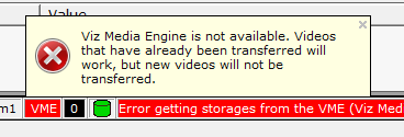
If the Viz One configuration is successful, a green Viz One icon will appear in the Status Bar.
Viz One Error Message
If the configuration is not working properly, the Viz One icon will be red. Scenarios where the icon is red can for example be a Viz One-search that fails, or a more serious error; a non-responsive Viz One with no video playout. In such serious situations where the Viz One is unavailable, the following Viz One error message will appear, stating that videos that have already been transferred to Viz will still work, but any new videos will not be transferred.
Configuring Viz One Server Time-out Handling
In the event of a network failure or other unforeseen events the Trio client can be instructed by scripting to switch to a backup Viz One server. In order to prepare for this you should:
-
Use the macro commands settings:set_mam_service_document_uri [uri [username password]] and settings:set_media_search_credentials username password to instruct the switch to an alternate Viz One server.
-
Update the active configuration (will also update the Media Sequencer VDOM) with the new publishing point using the command: channelcontrol:set_asset_storage <host-name> <storage-name>
-
Make sure that the timeout value for the Media Sequencer VDOM value mam/get_publishing_points_timeout is appropriate for your network environment. By default it is 10000 (ms), i.e. 10 seconds. If the value is too low, the settings:set_mam_service_document_uri command could possibly return with error without making the required change due to perhaps network glitches. Note that you will have to restart your Trio client for a change to this parameter to take effect.
In order to get or set the timeout value you can:
-
Get the current value with: settings:get_setting mam/get_publishing_points_timeout
-
Set the timeout with: settings:set_setting mam/get_publishing_points_timeout [VALUE IN MS]. To allow for (max) 15 seconds : settings:set_setting mam/get_publishing_points_timeout 15000
A basic switchover-script example:
settings:set_mam_service_document_uri http://MyNewVizOneServer/api settings:set_media_search_credentials MyUserName MyPassword channelcontrol:set_asset_storage MyNewVizOneServer The Video server