
Viz Trio User Guide
Version 3.2 | Published June 29, 2021 ©
Creating Scene Elements in Viz Artist
Creating scene elements primarily consists of two activities:
-
creating the graphics and
-
adding different Control plug-ins.
Control plug-ins are the binding links between Viz Artist and Viz Trio that allow properties to be exposed to the Viz Trio operator.
Scene elements can have varying complexity, with one or more tab fields, different types of animations, etc. Scene elements may also include placeholders that are non-graphical objects. These can in turn contain other scene elements, such as text objects.
This section covers the following topics:
Viz Artist User Interface
Open Viz Artist by clicking the Viz Artist button in the upper right corner of Viz Trio. At startup, the Viz Artist user interface contains:
-
Resources: Contains all the different objects stored on Graphic Hub (Viz 3.x); located in the upper left corner of Viz Artist under the Server tab.
-
Editors: Lets you modify the properties of an object; displayed in the upper right corner.
-
Scene tree: Displays all the elements in a scene and their hierarchy; displayed in the lower left corner.
-
Preview: Displays a WYSIWYG representation of what the graphics will look like on-air; located in the lower right corner.
Note: Scene builder tools generally use drag and drop actions.
Creating Graphics
Create scene elements with the building blocks available in the Viz Artist database.
Note: Building blocks are placeholders that contain different types of graphical elements and/or plug-ins. They are therefore also called containers.
Build the graphics by organizing the containers hierarchically in the scene tree pane and adjust the associated properties in the corresponding property editors. The tree structure constitutes a parent-child hierarchy in which all child containers inherit the properties of the parent container.
The building blocks you select will depend on the type and complexity of the design. A basic description on how to create scene elements in each of the categories follows below.
This section covers the following topics:
Creating a New Scene Element
-
Start Viz Artist
-
Select Scene view.
-
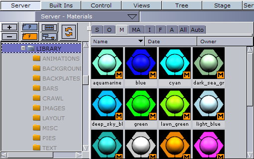
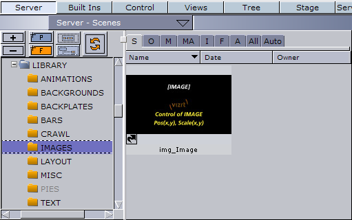
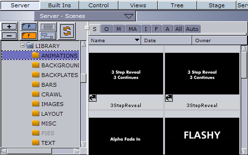
For Viz Artist 3.x: Click Server and select Scene from the drop-down in the upper left corner of the Database window and click the S tab.
-
For Viz Artist 2.x: Click Scene in the upper left corner of the Database window.
-
-
Locate and expand the LIBRARY folder in the folder tree.
-
The sub-folders displayed correspond to the various library categories in the Designer and contain the different scene elements created by the designer.
-
Note that scenes must be stored in the designated LIBRARY sub-folders in order to be available as scene elements in the Designer’s Resources pane.
-
-
Select the appropriate sub-folder (e.g. BACKGROUNDS).
-
Create a new scene.
-
For Viz Artist 3.x: Select Create... from the Scene database drop-menu, or press the CTRL + A keys.
-
For Viz Artist 2.x: Click the Add... button in the lower left corner of the Scene database pane.
-
-
Enter a name for the scene in the dialog box, and click OK.
-
The new scene becomes available at the right of the Server view.
-
Adding Group Containers

The Group function is a container that lets you group elements in the scene tree, and thereby create a parent-child hierarchy in which the child containers inherit the properties of its parents.
-
Open the scene (see To create a new scene element).
-
Add a group container to the scene tree.
Adding Geometries
-
Add a geometry object (e.g. Rectangle), and add it as a sub-container of the group container in the Scene Tree.
-
Rename the rectangle’s sub-container to for example background in order to describe its function.
Editing Scale and Position

-
Display the Transformation editor by selecting the Transformation icon on the container.
-
Modify the objects’s size and position.
-
The size and position of an object depends on the type of scene element you want to create. For example, a lower third or over the shoulder..
-
-
Specify the order of layered objects by using the Z field in the Position section.
-
Some objects, such as a background or a backplate, must be displayed behind the other elements in a scene in order to prevent blocking them.
-
Keep in mind that the object with the highest z-position will be displayed at the front, while the object with the lowest z-position will be displayed at the back (unless you are rotating objects on the y-axis, in which case you might need to manually sort objects on the Z-axis using the Z-sort plug-in).
-
Copying Containers
-
Press the CTRL key and the left cursor button simultaneously and drag the container to its new location.
-
For Viz Artist 3.x: A node symbol appears to the left of the copied container, indicating the position where the new container will be added when releasing the cursor button.
-
For Viz Artist 2.x: An arrow appears at the far left of the scene tree, indicating the position where the new container will be added when releasing the cursor button.
-
-
To copy multiple containers, press the CTRL key and select containers with the left cursor button. Drag and drop the containers to the new location.
Deleting Containers

-
Select containers to delete with the left cursor button and drag them into the trash can above the Renderer window, or
-
Right-click the container and select Delete Container <name> from the menu (Viz Artist 3.x only).
Adding Materials
-
Select the material (M) tab under the server view (Material button in Viz Artist 2.x), and drag and drop a material object into the container.
-
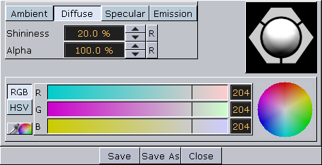
Double-click the material to open the Material Editor to change effects or lights (e.g. Ambient, Diffuse, Specular and Emission).
Adding Fonts
-
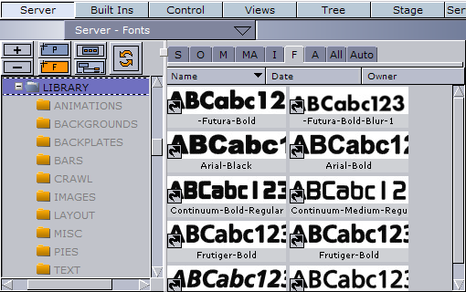
Select the font (F) tab under the server view (Font button in Viz Artist 2.x), and drag and drop a font into the container.
-
Open the transformation editor to change the size and position of the text.
Adding Images
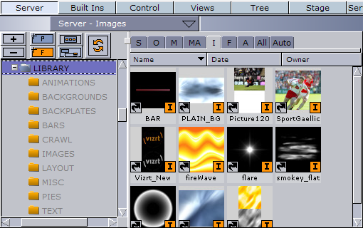
-
Select the image (I) tab under the server view (Image button in Viz Artist 2.x), and drag and drop an image into the container.
-
Open the transformation editor to change the size and position of the text.
Adding Key
In order to enable Viz Engine to produce a key signal, key must be added to individual containers that contain objects that should draw key or the scene in general.
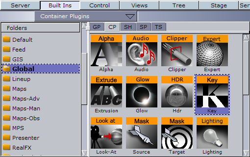
-
Click the Built Ins button, and select the Global folder from the Container Plugins (CTRL + 2).
-
For Viz Artist 2.x: Click Function.
-
-
Drag and drop the Key plugin into the containers that should have key.
Adding Control Plug-ins
To enable Viz Trio operators to edit the graphical elements, the containers must contain the necessary control plug-ins, which must be added for each of the graphical elements that are to be edited. The plug-in selected depends on the type of property that needs to be exposed for editing.
In addition to container specific plug-ins, the scene tree must contain a plug-in called the Control Object plug-in, which allows Viz Trio to identify a scene as a Viz Trio template.
Note: Only containers placed under the Control Object plug-in in a scene tree can be imported to Viz Trio.
Control plug-ins are added manually to the containers using drag and drop. The interaction principles are the same for all control plug-ins, except the Control Object plug-in which is added automatically if another control plug-in is added to the scene tree. Control Object can also be added manually.
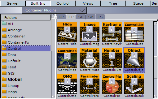
Adding a Control Plug-in
-
Click Built Ins, and select the Container Plugins (CTRL + 2) option from the drop-menu or click the CP tab.
-
For Viz Artist 2.x: Click Function, Container and select the Control folder.
-
-
Select a control plug-in and add it to the appropriate container.
-
Click the control plug-in icon to display the associated editor.
Defining Tab Fields
Viz Trio uses the control plug-in’s Field Identifier ID to identify the container as an editable element. In addition, the field’s ID defines a tab-field and is used to specify the tab-order between editable elements in a scene.
Note: All control plug-ins located in the same container must have the same field ID; this ensures that all associated property editors are enabled for selection when a tab-field in chosen.
To group properties located in different containers to the same tab-field, the property name must be added as an extension to the field ID, using the following format: ID.propertyname. For example, 2.scaling.
-
Add a control plug-in (e.g. Control Text) to the scene tree.
-
Open the control plug-in’s editor and set the Field Identifier.
-
The field identifier should be a numeric value (range 1-n).
-
Saving Scenes
Save and close scenes at the lower left corner of the Viz Artist interface.

-
Click Save to save a new scene or to overwrite an open scene, or
-
Click Save As to save it as a new scene.
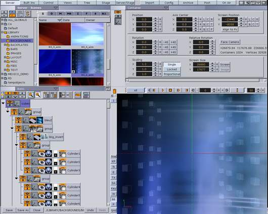
Creating Backgrounds
This section shows how to create a basic background with an image.
Note: The screenshots below are taken from Viz Artist 3. The user interface in Viz Artist 3 is similar to Viz Artist 2. Additional descriptions are provided where necessary.
-
Start by creating a new scene in the BACKGROUNDS directory in the Viz Artist scene tree (see how To create a new scene element).
-
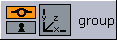
Double-click the new scene to open it, and add a group container to the scene tree (see how To add group containers).
-
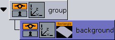
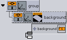
Add a new group as a sub-container to the first group, and name it background.
-
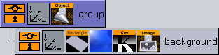
Add an object, in this case a rectangle, to the background container. The container should now have four icons; a show/hide, lock/unlock, transformation editor, and a rectangle icon (see how To add geometries).
-
Adjust the rectangle’s size and position (see how To edit scale and position ).
-
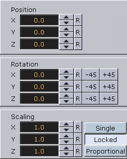
Click the Transformation button to open the Transformation editor.
-
Change the position in the Position section in the upper left corner of the Transformation editor.
-
Adjust the Z position in the Position section to ensure that the background is displayed behind all other elements in a scene. Remember that the Z position value of backgrounds must always be lower than the Z position value of the other scene element categories.
-
If the background contains animations, verify that they will not overlay the other objects at any point. A low z-position value such as -500 will normally be sufficient, but increase this as required.
-
-
Change the size of the rectangle to cover the whole area of the Renderer window to create a full-screen background. This is most easily done by pressing the Screen button available in the Screen Size section in the lower right corner of the Transformation editor. The rectangle will then be re-sized to cover the screen.
-
Add an image to the scene tree (see To add images).
-
Select an image and add it into the background container using drag and drop.
-
-
Add the key function to the background container (see how To add key).
-
In order for Viz Engine to produce a key signal, a key function must be added.
-
-
Add a Control Image plug-in to the background group; the Control Object plug-in will then be added automatically (see Adding Control Plug-ins).
-
Adding the Control Image plug-in allows the background object to be modified in Viz Trio in playout or design mode.
-
-
Define the tab-field. Select the Image icon on the container to display the Control Image editor. Enter an ID in the Field Identifier field, for example 1.
-
This creates a tab-field, which enables the user to edit any exposed properties. The image position and scaling can be exposed for editing if required.
-
-
Add a description of the background object. Select the Control Object plug-in icon on the group container. Enter a description of the background object in the Description field in the upper part of the editor (e.g. Background Still Image).
-
The description entered in the Description field is the same as that displayed when adding a scene element to the scene tree in Viz Trio’s Designer. Although optional, it's recommended to use the scene name as a description in order to provide a better overview.
-
-
Click Save to save the background object. Select the appropriate BACKGROUND directory in the Scene database to see the new scene icon.
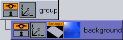
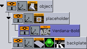
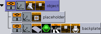
Viz Artist Scene Tree
Viz Trio Designer Scene Tree
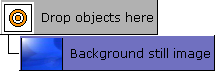
Info: After finishing the tutorial, the Viz Artist and Designer scene tree should look like the screenshots above.
Creating Backplates
Create a basic backplate with two text tab fields. For details on how to add animation to a backplate, see Creating Animations.
Note: The screenshots used below are taken from Viz Artist 3. The user interface in Viz Artist 3 is similar to Viz Artist 2. Additional descriptions are provided where necessary.
-
Start by creating a new scene in the BACKPLATES directory in the Viz Artist scene tree (see how Creating a New Scene Element).
-
Double-click on the new scene to open it. Add a group container to the scene tree (see how Adding Group Containers). Rename the container to object by double-clicking the label.
-
Add a new group as a sub-container to the first group, and name it backplate.
-
Add an object, in this case a rectangle, to the backplate container. The container should now have four icons: show/hide, lock/unlock, transformation editor, and rectangle. For more information, see Adding Geometries.
-
Adjust the rectangle’s size and position. For more information, see Editing Scale and Position.
-
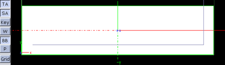
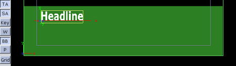
Scale and position the rectangle to create a backplate. Use the Title and Safe Areas as references when positioning the rectangle. The Title Area (blue box) is displayed by clicking the TA button in the lower left corner of the Renderer window, while the Safe Area (the green box) is shown by clicking the SA button.
-
-
Display the Transformation editor by selecting the Transformation button, located on the backplate container.
-
Scale the rectangle along the X and Y axes, and place it in the lower third area of the screen as shown in the screenshots.
-
The backplate should be able to be repositioned and scaled in the Designer and/or in playout mode. Complete accuracy in terms of scale and position are therefore not required here.
Note: Any rounded/beveled corners will be stretched if scaled.
-
-
Set a Z-value slightly below zero (e.g. 10) for the backplate.
-
For objects to be displayed in the front, always select zero or a higher value for the z-position. This will ensure that the scene elements are displayed in the correct layers and do not cover each other.
-
This value could be lower depending on the animations added later.
-
-
Add a material to the scene tree (see Adding Materials).
-
Select a material and add it to the backplate container using drag and drop.
-
To modify the color, display the Material editor by clicking the icon.
-
-
Add the key function to the background container. For more information, see Adding Key. In order for Viz Engine to produce a key signal, a key function must be added.
-
Add a new group as a sub-container to the object container, and name it placeholder. This will create a new empty group above the backplate container.
-
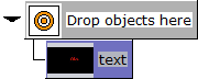
Add the Placeholder plug-in to the Placeholder container (see Adding Control Plug-ins).
-
The Placeholder for the object allows users to add scene elements such as text and images to the backplate.
-
-
Optional: Add a font object as a sub-container to the placeholder container to provide a visual cue while adjusting the position of the placeholder container.
Note: The font is a temporary visual cue that must be removed once you have finished adjusting the placeholder container.
-
Open the placeholder container’s transformation editor, and scale and reposition the placeholder object to form a headline as illustrated in the example below.
-
Adjust the Z-position in order to ensure that it will be displayed in front of the backplate. Generally a value slightly above zero will be sufficient.
-
When finished adjusting the placeholder object delete the font object as it is no longer needed (see Deleting Containers).
-
Add the Control Container plug-in to the node labeled object (see Adding Control Plug-ins).
-
This enables basic positioning control for the entire backplate, including the placeholder object.
-
The Control Container plug-in allows all child objects in the group to move simultaneously.
-
Select the Control Container icon to open the associated editor. Expose the X, Y, and Z position. The Field Identifier (1) is added automatically.
-
-
Add the Control Material plug-in to the node labeled backplate (see Adding Control Plug-ins).
-
Open the plug-in’s editor, and change the Field Identifier field to 1.material.
-
This will group the material property to tab-field 1 and allow the user to modify it together with the other exposed properties of the tab-field.
-
-
Add the Control Container plug-in to the node labeled backplate (see Adding Control Plug-ins).
-
Open the plug-in’s editor, and change the Field Identifier field to 1.scaling.
-
This will group the material property to tab-field 1 and allow the user to scale the backplate.
-
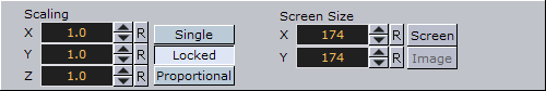
Expose the X and Y scaling.
-
Open the Transformation editor, and enable the Single option in the Scaling section to allow X and Y axes to be scaled separately.
-
-
Select the Control Object icon in the object container to open the Control Object editor. Enter a description in the Description field, for example Basic backplate.
-
Click the Save button to save the backplate object.
-
Select the appropriate BACKPLATES directory to see the newly created scene and the scene icon the Viz Trio operator will see in Viz Trio’s Designer.
Creating Text Objects
![]()
The screen shots used below are taken from Viz Artist 3. The user interface in Viz Artist 3 is similar to Viz Artist 2. Additional descriptions are provided where necessary.
-
Create a new scene in the TEXT directory in the Viz Artist scene tree (see how Creating a New Scene Element).
-
Rename the group container _object _(see Adding Group Containers).
-
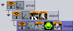
Add a font object to the scene tree as a sub-container of the object container, and rename the new container text.
-
Open the Text editor, and enter a common phrase (e.g. Abc).
-
Add the key plugin to the object element (see Adding Key). In order for Viz Engine to produce a key signal, the key plugin must be added.
-
Add a material to the text container (see Adding Materials).
-
Add the Control Text and the Control Material plug-in to the text container. This allows the Viz Trio operator to edit the text (see Adding Control Plug-ins).
Note: Control Object is automatically added to the scene tree’s root container.
-
Select the icon to display the Control Text editor.
-
The Field Identifier (1) has been added automatically, thereby creating a tab-field.
-
Expose the kerning, font, and justification by clicking the corresponding buttons. Set other options if needed.
-
-
Select the icon to display the Control Material editor. The Field Identifier (1) has been added automatically, thereby creating a tab-field.
-
Provide a description for the text object. This must be done in the Control Object editor.
-
Select the Control Object icon in the object container to open the editor.
-
Enter a description for the text object in the Description field, for example Plain Text.
All scene elements available in Viz Trio Designer’s resource library are represented with icons reflecting the appearance of the saved scene. All graphical elements are reduced proportionally in size, and will therefore appear very small on the icon.
In order to create an icon with a good enough visualization of the scene, a dummy scaling group can be created at the root level of the scene tree. This will allow the graphical representation of the scene to be enlarged without changing the actual size of the actual scene objects.
-
-
Add a group to the root level of the scene tree. This will create an empty group container at the same level as the object container.
-
Select the object container and append it as a sub-container to the newly added group container. As the object group with its Control Object is moved, it will not be used in the Viz Trio Designer. This will allow you to create a good visual representation of the library element.
-
Open the transformation editor for the group container.
-
Position the text object to the lower left corner of the Renderer window.
-
Increase the scale of the text object until it fills the whole Renderer window.
-
Click the Save button to save the text object. Select the appropriate TEXT directory in the Scene database to see the new scene icon.
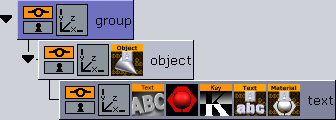
For reference: After finishing this quick tutorial, the Viz Trio Designer scene tree should look like the image below.
Creating Image Objects
Note: The screen shots used below are taken from Viz Artist 3. The user interface in Viz Artist 3 is similar to Viz Artist 2. Additional descriptions are provided where necessary.
-
Create a new scene in the IMAGE directory (see Creating a New Scene Element).
-
Add a group container to the Scene Tree (see Adding Group Containers).
-
Rename the group container to object.
-
Add an image to the scene tree as a sub-container of the object container. The container is automatically named the same name as the image. Rename the container image.
-
Add the key function to the object element (see Adding Key). In order for Viz Engine to produce a key signal, a key function must be added.
-
Add the Control Image _plug-in to the _image container, which will allow for image changes (see Adding Control Plug-ins).
Note: Control Object is automatically added to the scene tree’s root container.
-
Add text or an image that will act as an icon for the container with the _Control Imag_e editor.
-
The Field Identifier (1) has been added automatically, thereby creating a tab-field.
In order to create a scene icon with a large and good enough visualization of the image object, a dummy scaling group can be added. This allows the graphical representation of the icon in the scene tree to be large enough without changing the actual size of the image object to be used in the template.
-
-
Add a Group to the root level of the scene tree. This will create an empty group container at the same level as the object container.
-
Select the object container and append it as a sub-container to the newly added group container (now top node).
-
Select the Transformation icon in the group container to display the Transformation editor.
-
Increase the scale of the image object until it fills the whole Renderer window.
-
-
Open the Control Image editor, and expose image position and scaling by clicking the corresponding buttons. Set other options if needed.
When having specified the parameters, various additional control plug-ins can be added to the image object. Selection of the control plug-ins depends on the effect to be created. Refer the Viz Artist User Guide for further details on the different control plug-ins. -
Select the Control Object icon in the object container to open the editor. Enter a description for the image object in the Description field. For example New Image Object.
-
Click the Save button to save the image object. Select the appropriate IMAGE directory in the Scene database to see the new scene icon.
For reference: After finishing this quick tutorial, the Viz Trio Designer scene tree should look like the image below.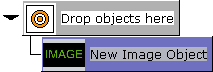
Creating Animations
The process of creating an animation object follows the same principles as when adding an animation to graphic elements in ordinary Viz Artist scenes. Basically the only difference is that the animation is added to an empty container without any graphic elements.
Note: Screen shots used are from Viz Artist 3. The user interface in Viz Artist 3 is similar to Viz Artist 2. Where needed additional explanation is given.
-
Create a new scene in the ANIMATIONS directory (see how To create a new scene element).
-
Add a group container to the scene tree (see how To add group containers).
-
Add a group container to the scene tree as a sub-container of the group container, and rename the new container to object.
-
Create a slide-in animation on the object container. To create a slide-in animation the object container’s position must be changed. Initially the graphics can be off screen by moving it to the far left.
-
Open the object container’s transformation editor, and specify the container’s initial X-position in the Position X field (e.g. -600).

-
Verify that the timeline field in the timeline editor, seen above the Scene Editor, is set to 0 (fields).
-
Click the Set Key button (aka Update in Viz Artist 2). This creates a keyframe reflecting the scene as is. The number of fields specified in the timeline field is automatically updated to 50, which is the default interval.
-
In the Transformation editor, reset the Position X to 0.
Tip: Click the R (reset) button to the right of the Position X field.
-
Click the Set Key button again to create a new keyframe.
-
This creates a simple in-animation.
-
The values at these keyframes are called keys. Viz Artist calculates the interpolated values between each key to produce the completed animation.
-
-
Create an out-animation that slides the object out the same way it came in (e.g. Position X set to -600).
-
Click the Set Key button again to create a new keyframe.
-
Viz Artist calculates the interpolated values between the second and third keyframes to produce the completed out-animation.
Creating the animation adds an animation icon to the object container. Clicking the icon displays the Stage editor, which allows for further tuning of the animation.
In order to ensure that the animation stays on screen for as long as required, a stop point at the end of the in-animation can be added, which in this case would be at field 50 in the timeline. The stop point will prevent the out-animation from playing before a Continue command is issued.
-
-
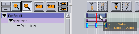
Open the Stage editor by selecting the animation icon (wheel) on the object container.
-
The animation channel is represented by a gray (Viz Artist 3) or green (Viz Artist 2) line in the right part of the Stage editor.
-
The keyframes are indicated by small rectangles.
-
-
Move the red Timeline Marker, represented as a vertical red line, to the second keyframe (the in point).
-
Select the Default director as illustrated in the example above.
-
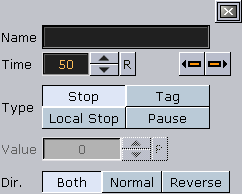
Click the Add a Stop/Tag button (aka Add Stop button in Viz Artist 2.x).
-
It's now possible to see the stop point just added to the Default director.
-
-
Select the Stop point to open the editor__to see, and if needed, adjust the parameters for the stop point.
-
Verify that the stop point has the same time settings as the second keyframe.
-
-
Add Control Object _plug-in to the _object container (see Adding Control Plug-ins).
Note: Since the animation object is created without the need for graphic elements, there is no need to expose properties for editing; however, Control Object is needed as it provides a description for the animation object.
-
Open the Control Object editor, and enter an appropriate description to the Description field.
-
Add a Group container to the scene tree as a sub-container of the object container, and rename the new container to placeholder.
-
Add the Placeholder plug-in to the Placeholder container (see Adding Control Plug-ins).
-
The Placeholder for the object allows users to add scene elements such as backplates, text, and images to the animation.
Note: The animation object contains no graphical elements, hence, saving the scene will create a blank scene icon when viewed in Viz Trio.
-
-
Create a dummy container with graphics illustrating the animation and apply this as a scene icon.
-
This will easily distinguish one animation scene from another in Viz Trio.
Tip: In order to provide a graphical illusion of the animation sliding in from the left, a built-in arrow object can be used.
-
-
Add a geometry, in this case an arrow, to the scene tree (see To add geometries).
-
Level the Arrow container with the group container to ensure that the arrow graphics are not displayed on screen during Playout.
-
Open the Arrow editor to set the style and size of the geometry.
-
Open the Arrow container’s transformation editor to scale and reposition the arrow to illustrate it coming in from the left.
-
Add material, images and text if needed.
-
-
Click the Save button to save the animation object. Select the appropriate ANIMATIONS directory in the Scene database to see the new scene icon.
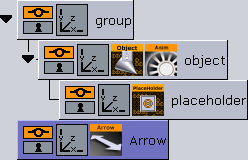
For reference: After finishing this quick tutorial, the Viz Trio Designer scene tree should look alike the image below.
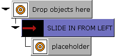
Note: SLIDE IN FROM LEFT refers to the control object plugin’s description field, and placeholder to the placeholder plugin’s description field.
See Also