
Viz Artist User Guide
Version 3.12 | Published October 17, 2019 ©
Parameters for Perspective View
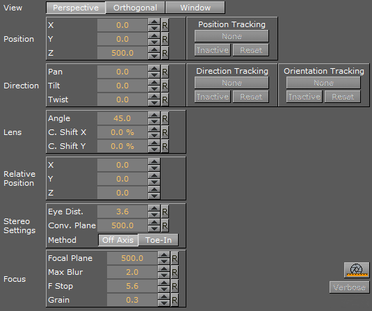
Position
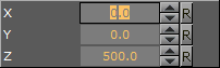
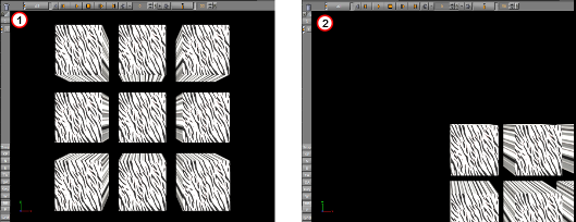
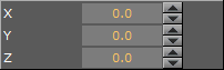
Set the position of the camera along the X, Y, and Z axis. Default setting (1) and modified setting (2)
Direction
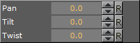
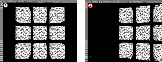
Set the values for Pan, Tilt, and Twist. Pan set to 0 (1). Pan set to 15 (2).
Lens
-
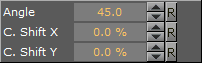
Angle: Sets the Camera field of view angle (1).
-
C. Shift X: Shifts the center of the lens on the X axis.
-
C. Shift Y: Shifts the center of the lens on the Y axis.
Relative Position
Set the position of the camera along the X, Y, and Z axis, relative to a real camera. Entering a value in for X, Y and Z axis for the Relative Position changes the actual camera position values, but relative to its orientation.
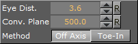
Stereo Settings
Available if set in Camera Properties (see the Configuring Viz section of the Viz Engine Administrator Guide).
-
Eye Dist.: Fine-tunes for individual users. A higher value results in more depth whereas a lower value flattens the image.
-
Conv. Plane: A higher value for the zero parallax distance means that objects appear to come closer to the viewer, a lower one pushes the graphics to the back.
-
Method:
-
Off Axis: Creates a distortion-free stereo pair. This is the preferred option.
-
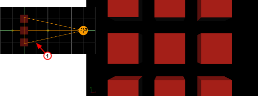
Method Toe-In: Points the cameras slightly inwards towards each other so that the lens axes converge at a single point (“vergence point”). Objects in the same plane as the vergence point show to be closer to the plane of the image, with other objects seeming to be behind or in front of this point. These values must be set during production in accordance with the convergence values used for the cameras.
-
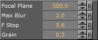
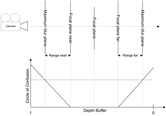
Focus
Focus settings are available if the Depth of Field parameter is set to Active.
-
Focal Plane: Defines the distance between the camera and objects which are in focus.
-
Max Blur: Sets the size of maximum blur furthest from the camera. For example, a value of 20 signifies that a pixel is enlarged to a size of 20 pixels.
-
F Stop: Sets the F-Stop value (relative aperture): The lens model used by the depth of field algorithm mimics a real lens behavior
-
Grain: Defines the blur level.
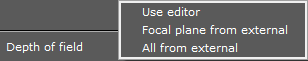
Depth of Field
Depth of Field (DOF) can be set in the Camera (see the Configuring Viz section of the Viz Engine Administrator Guide) Configuration. There are three options:
-
Use editor: Allows free positioning of the focal plane. The F-Stop must be adjusted manually.
-
Focal plane from external: Gets the focal plane information from the lens file, and must be calibrated separately. Select this option to have the DOF follow the camera's focus.
-
All from external: Gets focal plane information from the tracking system.
To Set DOF to Follow the Camera Focus
-
Set the Depth of field to Focal plane from external.
-
Adjust the Max Blur. This value doesn't need to be higher than 12 to give a good result.
-
Adjust the F-Stop. Changing the iris also changes the range of depth. Try a value around 10.
-
Adjust the Grain. This value sets the noise and influences the DOF. Try a value between 0.001 and 0.003.
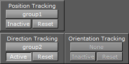
Tracking
A camera can be set up to track the Position, Direction or Orientation of a Container.
-
Position Tracking: The position of the camera is the same as the target containers position.
-
Direction Tracking: The rotation of the camera is updated to always point towards the current position of the target container.
-
Orientation Tracking: The rotation (orientation in space) of the camera is the same as the target containers rotation (orientation in space).
Note: Direction and Orientation tracking cannot be used at the same time. The results would contradict each other (both of them result in a potentially different rotation value for the container).
-
Active/Inactive: Drag a container to the drop zone to automatically enable camera tracking. To disable tracking, click the Active/Inactive button.
-
Reset: Disables camera tracking.
Miscellaneous Buttons

-
Lens File Calibration Editor: Opens the Lens File Calibration Editor.
-
Verbose: Linked to cameras in Virtual Studio. For more information about the Virtual Studio option see the Virtual Studio documentation.
Avoid Artifacts
To avoid artifacts, avoid using maximum blur levels which are higher than 30 pixels. A blur radius of 30 pixels creates rather blurry results which should be sufficient. It is possible to increase this maximum radius, but this also increases the rendering time.
Set the clipping planes in the range you really need for the scene. So if your scene has only a depth of 200, set the far clipping plane to 250 or a similar value. Since the depth of field shader takes the depth from the depth buffer, this gives more accurate results. Try to avoid high blur levels for objects before the focal plane, as this can cause unwanted effects. You can increase performance, but artifacts would show for blur levels lower than 30px.
See Also