Viz Artist User Guide
Version 5.0 | Published December 20, 2022 ©
Create an Over the Shoulder Scene
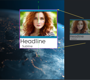
An Over the Shoulder (OTS) graphic is a graphic which is placed over the shoulder of, for example, the news anchor, and can show on the left or right side of the screen. An OTS graphic can be used to highlight a story with a large image and a headline, and sometimes a sub-headline.
This section contains information on the following procedures, which when completed in sequence create an OTS Scene:
To Create a Scene
Create a new scene and save it as OTS.
To Add an Image and Basic Geometries
-
Add a Rectangle geometry to the Scene Tree.
-
Add an image (for example, a headshot) to the Rectangle container.
-
Open the Image Editor, set the mapping to vertex.
-
Open the Geometry Editor to set the Rectangle Width and Height to match the image proportions.
-
-
Rename the Rectangle container to Image.
-
Add a Cube geometry to the scene. Place it above the Image container.
-
Open the Cube plug-in editor and do the following:
-
Set Center Y to Bottom.
-
Adjust the Size X value to fit the width of the image.
-
Adjust the Size Y value to 10.0.
-
Adjust the Size Z value to 1.0.
-
-
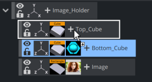
Copy the Cube container. Place it below the original Cube container.
-
Press CTRL + C then CTRL + V to place a copy below the original container.
-
Press CTRL + Left mouse button to drag and drop a copy to a new location.
-
-
In the transformation editor of the Cube container, set Center Y to Top.
-
Rename the Cube containers to Top_Cube and Bottom_Cube.
-
Open the transformation editor of each Cube container and move the position of the Cubes. Place one above and the other below the image.
-
Group all containers under a new root container:
-
Select all containers and click the Group button, or
-
Select all containers and press CTRL + G
-
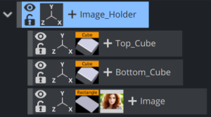
-
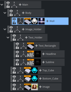
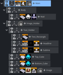
Rename the new group container to Image_Holder.
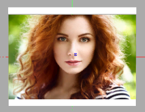
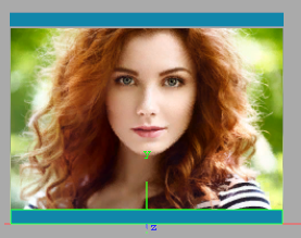
Scene Tree
Output
Note: Geometries can also be scaled with the container’s transformation editor. But this has an effect on the its proportions when, for example, beveled edges are added.
To Add Materials
-
Open the OTS scene.
-
Expand the Image_Holder container.
-
Click the + button and type material.
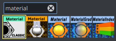
-
Open the Material Editor and define a color (for example, blue or red).
-
Copy the Material onto the Bottom_Cube container:
-
Drag the Material from one container to the other, or
-
Right-click the Material and from the context menu select Copy MATERIAL and then Paste MATERIAL onto the receiving container.
Scene Tree
Output
-
To Scale Geometries and Place Them in Z Space
-
Add a new group container. Place it above the Image_Holder container:
-
Select the Image_Holder container and press CTRL + INSERT, or
-
Drag the New Group button to the Image_Holder container.
-
-
Rename the New Group container to Body.
-
Add a Rectangle geometry to the scene. Place it as a sub-container of the Body container.
-
Rename the new container to Wall.
-
Open the Rectangle editor (not the transformation editor) and do the following:
-
Set the Center option to Center.
-
Adjust the Height value to 450 (for example).
-
Adjust the Width value to 800 (for example).
-
-
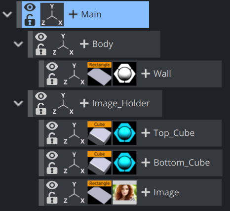
Group the Body and Image_Holder containers under a new container:
-
Select the Body and Image_Holder containers and click the New Group button, or
-
Select the Body and Image_Holder containers and press CTRL + G (when Caps Lock is disabled).
-
-
Rename the new group container to Main.
-
Copy the Material from one of the Cube containers to the Wall container.
-
Open the Body container transformation editor.
-
Adjust the Position Z value to -30.0 (This avoids potential conflicts with the geometries in the Image_Holder container).
Note: If the position and/or scaling of the Wall geometry need to be adjusted, make sure to adjust those values on the Body container, as this keeps future additions to the container aligned.
To Add Text
-
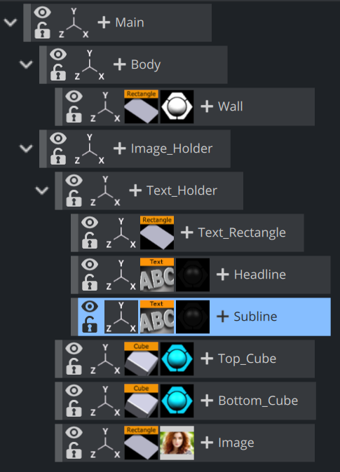
Add a New Group container. Place it below the Image_Holder container.
-
Rename the New Group container to Text_Holder.
-
Add a Font to the scene. Place it as a sub-container of the Text_Holder container.
-
Copy the Font container. Place it below the first Font container.
-
Rename the Font containers to headline and sub-headline.
-
Open the Classic Text Editor of both containers and do the following:
-
Enter some text (for example, headline, sub-headline).
-
Set the Orientation option to Center.
-
-
Open the transformation editor of the headline and sub-headline containers and scale and position the containers to fit each other.
-
Add a Rectangle geometry to the scene. Place it above the Font containers and rename it to Text_Rectangle.
-
Open the transformation editor of the Text_Rectangle container and do the following:
-
Adjust the Position Y value. Center the rectangle between the text objects.
-
Enable single (S) Scaling.
-
Adjust the Scaling X value to equal the width of the image.
-
Adjust the Scaling Y value to 0.1 (for example).
-
-
Copy the Material from one of the Cube containers to the Text_Rectangle container and modify if necessary.
-
Open the transformation editor of the Text_Holder container and do the following:
-
Adjust the Position Y value to equal the Image_Holder objects.
-
Adjust the Scaling (Locked) if needed.
-
|
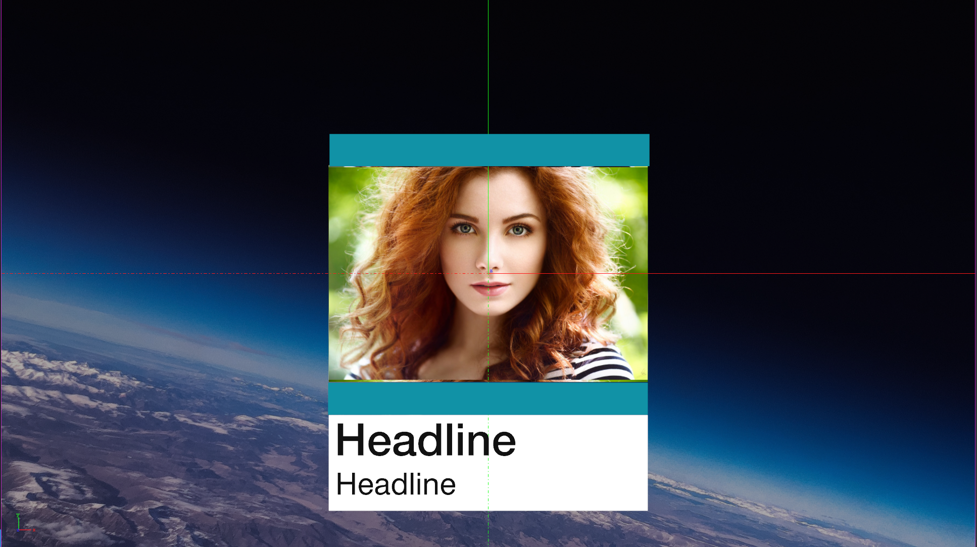
Scene Tree |
Output |
|
|
|

Note: If the position and/or scaling of the font containers need to be adjusted, make sure to adjust those values on the Text_Holder container, as that keeps future additions to the container aligned.
To Add Background Items
This procedure details how to add a background image with moving effect.
-
Apply a suitable image to the Wall object. This can have either an Alpha channel assigned or it can be shown as Fullscreen. Don't forget to set the mapping to vertex.
-
Open the transformation editor and do the following:
-
Adjust the Scaling values as required.
-
Adjust the Position Z value (for example, 2.0) so that it shows in back of the foreground objects.
Scene Tree
Output
Note: If the position and/or scaling of the background items as a group need to be adjusted, make sure to adjust those values on the Body container, as that keeps future additions to the container aligned.
-
To Animate
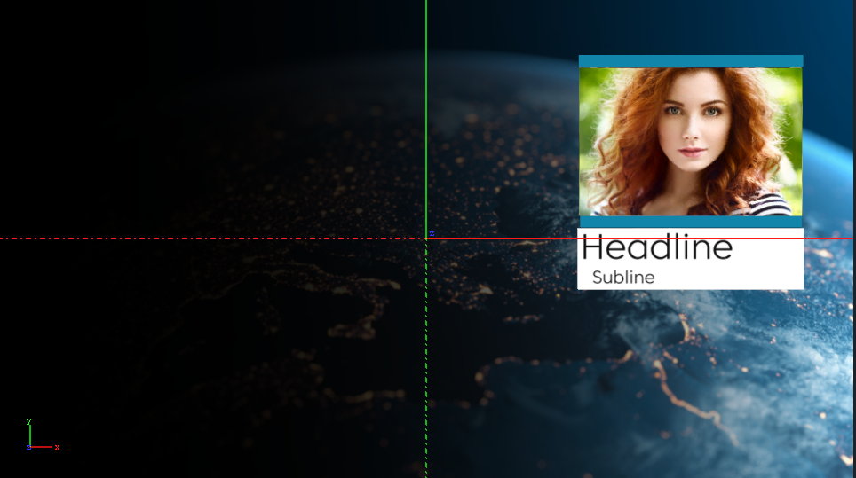
Before animations are added, move the OTS graphic to its final on-screen position (normally to the top left or right) where it should be seen by the viewer.
-
Open the OTS scene.
-
Open the transformation editor of the Main container.
-
Adjust the Scaling, Rotation, and Position values. Make sure any conflicts are resolved now. Notice that when the Scene is rotated, objects may drift apart as they are placed at different depths (Z space).
-
Save the scene. This procedure focuses mainly on the animation of a root container, mainly to start with the simplest factor (how do I want my graphics to animate into view?).
-
Open the OTS scene.
-
Set Key Frames to 60/50 (for example) fields.
-
Click the Set Key Frame button.
-
Open the transformation editor of the Image_holder container and adjust the Position X value so that the OTS element is off screen.
-
Set Key Frames to 0 fields.
-
Click the Set Key Frame button.
Note: Notice that an Animation object has been added to the Main container.
-
Change the Position X back to the final destination, hit the Set Key Frame button.
-
Click the Start animation button on the Time-line Editor. The graphic now moves from Position X at 0 fields to its final on-screen position.
-
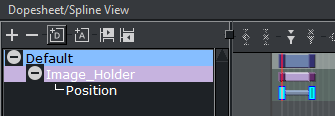
Open the Stage Editor. The Image_Holder container and the animated Position property are located under the Default Director.
-
Right-click the Image_Holder container and from the context menu select Transformation > Scaling. This adds a time-line for the Scaling property of the Main container.
-
Click the first Key Frame on the Scaling animation’s time-line on the Dopesheet Editor. This opens the Scaling animation Stage Object Editor.
-
Set the Scaling values to 0.5.
-
Click the Start animation button on the Time-line Editor. The graphic now animates from Position X at 0 fields with Scaling at 0.5 to its final size on-screen.
Note: If the Viz Configuration is set to 50 hertz the default animation time-line is 50 fields. If set to 60 hertz, it is 60 fields. It is always important to configure the required output format before work is started on the designs.
To Animate Sub Containers
This procedure focuses on the animation of a sub-containers. In this case the image and text holder containers.
-
Open the Stage Editor.
-
Drag the Text_Holder container onto the Default Director.
-
Right-click the Text_Holder container and select Transformation > Scaling from the context menu. This adds a time-line for the Text_Holder container’s scaling property.
-
Set values for the Start and End keyframe
-
Click the Key Frame for the Scaling animation. In the Key Frame Editors set it to 30 (for example) fields, to delay the introduction of the Head and Subline.
Note: The Image_Holder and Text_Holder containers are set to grow from the Center. To grow the containers from other angles, open the transformation editor, for each container, and adjust the Axis Center properties. If the OTS is placed to the right, try setting the Text_Holder container’s Axis Center X to R (Right), and conversely.
Note: Always scrub the time-line in the time-line editor to check for potential conflicts (caused by rotation of objects).
To Animate Single Containers
This procedure focuses on the animation of a single container, and how to add additional Key Frames to the animation. In this case the background image is animated and an additional Key Frame is added to grow the size of the background image before it shrinks back to its final size.
-
Open the OTS scene.
-
Select the BackgroundImage_Holder container.
-
Set the number of fields to 30 in the Time-line Editor.
-
Open the Transformation Editor of the BackgroundImage_Holder container.
-
Set Scaling to 0.0.
-
Click the Set Key Frame button.
-
Set Scaling to the original value.
-
Set the number of fields to 60 in the Time-line Editor.
-
Click the Set Key Frame button.
-
Open the Stage Editor.
-
Select the Scaling animation time-line for the BackgroundImage_Holder.
-
Move the Time-line Marker to a position closer to the end of the animation.
-
Click the Add a Key Frame button.
-
Click the new Key Frame and set the Scaling value to be larger than the final size.
-
Save the scene.
Note: Always scrub the time-line in the time-line editor to check for potential conflicts (caused by rotation of objects).
To Animate Single Objects
This procedure focuses on the animation of single objects. Animating single objects increases the dynamics of the scene, especially when the scene has reached its final position on-screen and all other animations have stopped.
This procedure describes how to make a flare move, continuously, along another object.
-
Open the OTS scene.
-
Open the Stage Editor.
-
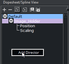
Create a new Director and name it Loop:
-
Click the +D button, or
-
Right-click the Stage Tree and select Add Director.
-
-
Select the Loop Director.
-
Set the Time-line Editor to 0 fields.
-
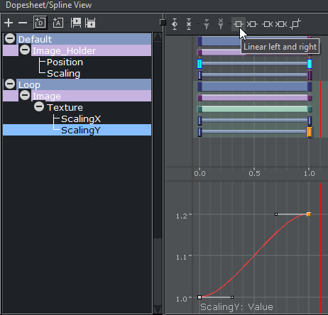
Open the Texture Editor of the Image:
-
Set Scale X and Scale Y to 1 and click the Set Key Frame button.
-
Set Scale X and Scale Y to 1.2 and click the Set Key Frame button.
-
-
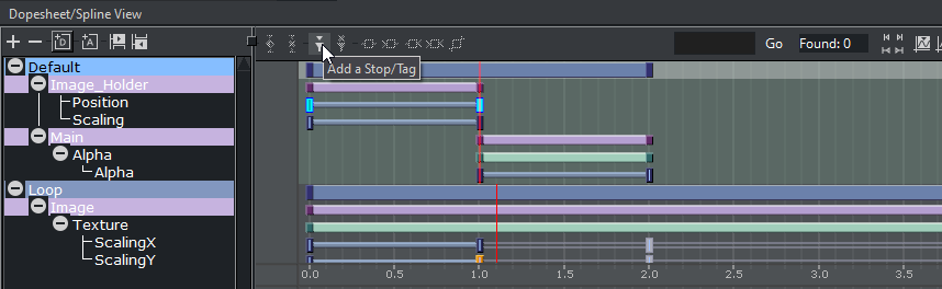
Select both of the ScalingX and ScalingY Key Frames and click the Linear left and right button.
-
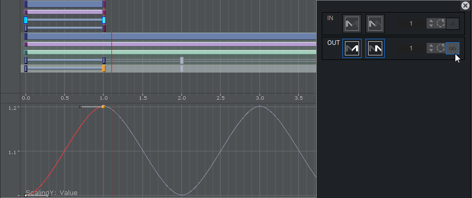
Click the ScalingX and ScalingY channel to open its Channel Editor. Click the Loop out and Infinite buttons.
-
The time-line should now look similar to the image above. Save the scene.
To Animate out
Animations to the scene so far has brought the graphic on-screen for the viewer to see. However, the scene should also be able to animate out instead of simply removing it (hard cut). This can be achieved in three ways:
Note: With one or a combination of the following three methods an out animation can be created. The scene now works in terms of animation, however, it does not work well if someone needs to control, for example, when or how the out animation should start. For this we need to add controls (using control plug-ins) that allows an operator to control the scene On Air.
To Fade out the Graphic with the Alpha Plug-in
-
Add the Alpha plug-in to the Main container.
-
Set the time-line to the end of the in animation (at 60 fields for example). Be sure to use the Default director
-
Open the Alpha plug-in editor.
-
Set the Alpha value to 100%.
-
Click the Set Key Frame button.
-
Set the Alpha value to 0%.
-
Click the Set Key Frame button.
-
Now we need to add a stop event. This ensures one can take the graphics in, then it is paused until the operator continues the animation which then plays the out animation.
-
Place the timeline cursor to time 1.0 (where all is animated in) and add a stop event.
When played, the animation animates in, stops at position 1.0 and after clicking on the continue button fades out to Alpha at 0%.
Note: The placed pilot1 stop/tag point on the Default Director’s time-line, at a given field, enables Vizrt control applications to create a thumbnail and show it in, for instance, the playlist.
To Add Controls
Stop/tag points are added to the Director to allow the operator to control the animation. However the operator, when required, should be able to control the content of the Scene. For this purpose Control plug-ins are used.
In our example we would like to control the image and the Head and the Subline text. Therefore, we need to add control plug-ins to the respective containers.
-
Open the Plugins Panel and search for Control Image.
-
Drag it to the Image container.
-
Click on the plug-in and give it a unique identifier (for example, 100).
-
Search for Control Text.
-
Drag the plug-in to Headline container.
-
Drag the plug-in to Subline container.
-
Give both plug-ins a unique identifier (for example, 101 for headline, 102 for Subline).
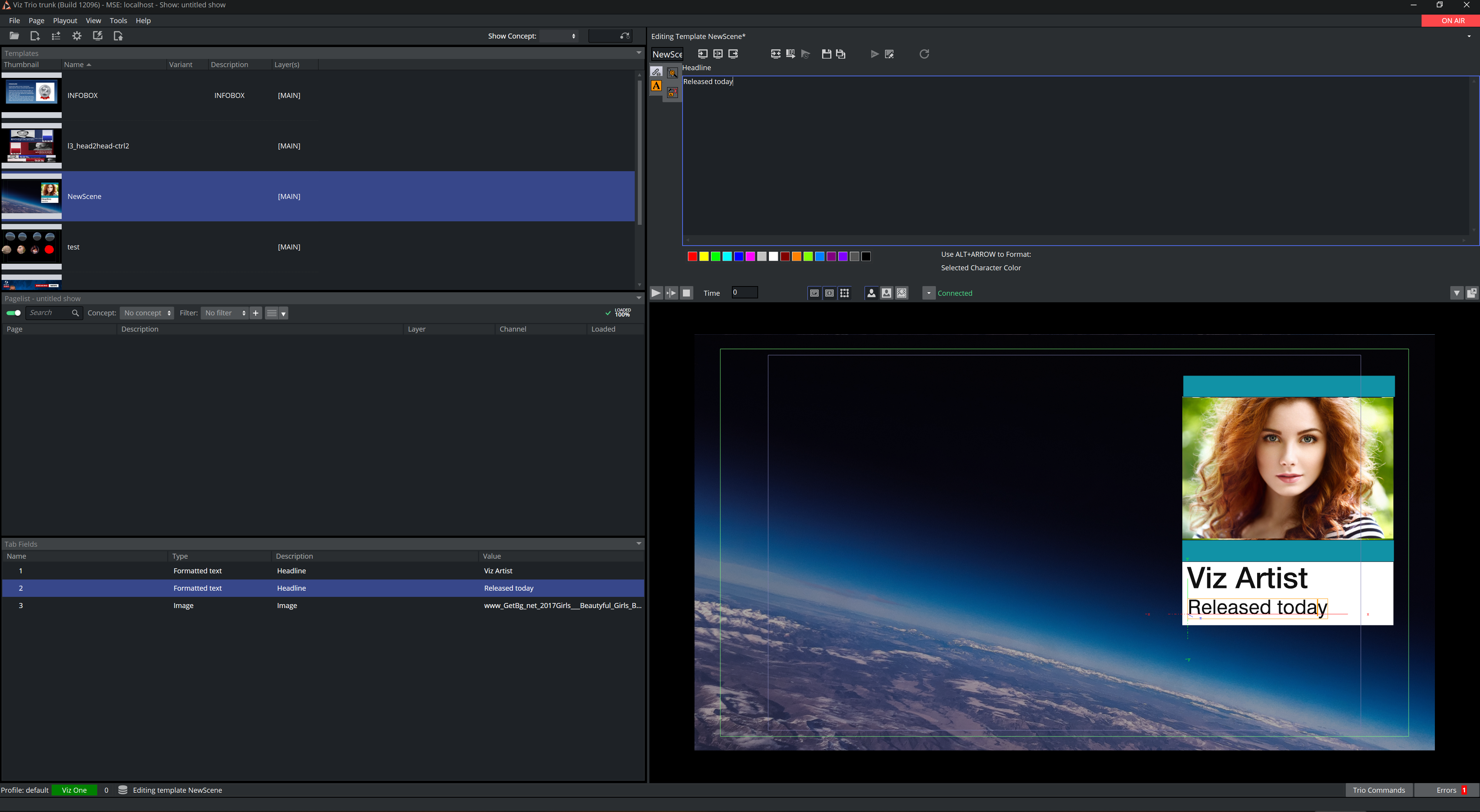
If this scene is now imported in, for example, Viz Trio, an operator is able to fill in the control values:
Tip: Number the Field Identifiers to help order them in the control application interface.
Note: To check that an operator can use the scene test it with a control application (for example, Viz Pilot with the Template Wizard, Viz Trio, Viz Channel Branding).