
Viz Artist User Guide
Version 5.0 | Published December 20, 2022 ©
Key Frame Editors
The Key Frame editors show details about the selected Key Frame. To view the Key Frame editor click on a Key Frame. Make sure that the Stage Object Editor is enabled.
This section contains information on the following topics:
Common Key Frame Editor Properties
-
Name: Defines the name of the Key Frame. This name is used for external commands or scripts.
-
Time: Defines where along the time-line (in fields) the Key Frame is placed.
-
 Previous/Next buttons: Selects the previous or next Key Frame along the time-line if the property has more than one Key Frame.
 -
Value: The rest of the Key Frame editor options vary according to which property is being animated.
Example: For scaling, it is possible to define the size of an object in direction X, Y, and Z.
Locked and Unlocked Key Frames
By default the Key Frames in the position animation are locked. They store information about the position of the container along the X-, Y- and Z-axis, as well as the time the Key Frame passed by in the animation.
An unlocked Key Frame stores only information of the position along X-, Y- and Z-axis, without the information at which time the Key Frame should be passed. To reflect this, in the object editor for a locked Key Frame the Time is grayed out. Furthermore, as the spline editor shows time and path-percentage, the unlocked Key Frames are not shown there. In the animation editor, unlocked Key Frames are shown at half height of locked Key Frames. Viz Artist calculates the time the Key Frame is passed to fit with the handles set in the next locked Key Frame before and after the unlocked Key Frame.
To better understand the difference between locked and unlocked Key Frames, create a simple position animation. You see the container moving with different speeds between the Key Frames. Next unlock all Key Frames and play the animation once more. The container moves evenly during the whole animation.
Use an unlocked Key Frames to define the path without editing the time for every Key Frame. This can save time.
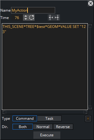
Action Key Frame Editor Properties
In addition to the common key frame editor properties, the Action Key Frame Editor defines the Action Channel. The action works when the Director time-line equals the Action Channel Key Frame.
-
Command: Executes the command or OS task entered here.
-
Type: Initializes action Key Frames for two main types of actions:
-
Command: Use Viz Artist internal commands to execute a number of automated tasks in the program (for Viz Artist internal commands documentation go to: <viz install folder>/Documentation/CommandInterface/index.html)
-
Task: Enter a task command. Any relevant command which can be started from a command line window (cmd.exe) can be executed as a task. If the path to the executable file contains spaces, set the complete path in quotation marks, for example, " C:\program files\microsoft office\office\winword.exe"
Tip: Multiple commands can be executed in the Action Key Frame Editor. The commands must be terminated by a ; (semi-colon) and on a new line. For example: RENDERER*TREE*$sometext*GEOM*TEXT SET Hello World; MAIN_SCENE*STAGE*DIRECTOR*$Default GOTO_TRIO $B $A;
-
-
Dir: Sets which way, forwards or backwards, the animation should go to trigger the Action Key Frame:
-
Both: The Key Frame is triggered when the animation goes forward and in reverse.
-
Normal: The Key Frame is triggered when the animation goes forwards.
-
Reverse: The Key Frame is triggered when the animation goes backwards.
-
-
Execute: Starts the action.
Examples of Commands for Action Key Frames
Here are some examples of Viz Artist internal commands, which can be used in the Action Key Frame Editor to create actions:
-
THIS_SCENE: The created action acts on this Scene only.
-
THIS_EDITOR: The created action acts on this Editor only.
-
THIS_DIRECTOR: The created action acts on this Director only.
-
THIS_PARENT_DIRECTOR: The created action acts on this Parent Director only.
Example of Invoking a Script Function
THIS_SCENE*TREE*$[name of the container]*SCRIPT INVOKE [your function name/sub routine name in the script]Example of Setting a Plug-in Value
THIS_SCENE*TREE*$[name of the container where the plug-in resides]FUNCTION[name of plug-in]*[name of UI item of the plug-in, (the button or the drop down list)] SET [value]Position Key Frame Editor Properties
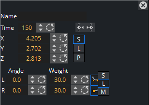
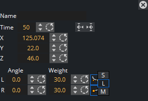
In addition to the Common Key Frame Editor Properties, a Position Key Frame contains information about the position of a Container at a specific time. The parameters of Position Key Frames are:
-
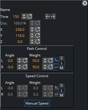
Distance: Defines the distance of a selected Key Frame (value in percent) between the first and last Key Frame of the animation (information only).
-
X: Defines the position along the X axis.
-
Y: Defines the position along the Y axis.
-
Z: Defines the position along the Z axis.
Path Control
-
Angle: Defines the angle of the handles for the path.
-
Weight: Defines the weight of the handles for the path.
-
 Smooth Left/Right: Allows the handles for the path to be smooth or linear (see Channel Editor).
 -
S / L / M: Defines the way handles for the path should be modified:
-
S (Single): Only the left or right parameter can be adjusted.
-
L (Locked): Left and right parameters are locked in their current position and adjustment changes both left and right parameters together.
-
M (Mirror): The left and right parameters are mirrored when adjusted
-
Speed Control
-
Angle: Defines the angle of the handles for the speed.
-
Weight: Defines the weight of the handles for the speed.
-
 Smooth Left/Right: Allows the handles for the speed to be smooth or linear.
 -
S / L / M: Defines the way handles for the speed should be modified:
-
S (Single): Only the left or right parameter can be adjusted.
-
L (Locked): Left and right parameters are locked in there current position and adjustment changes both left and right parameters together.
-
M (Mirror): The left and right parameters are mirrored when adjusted
-
-
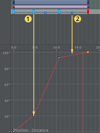
Manual Speed: Toggles the Key Frame Active or Inactive:
-
Active: Unlocks Speed Control (1). The speed between the previous, selected, and the next Key Frame is calculated by the position and the speed control of this Key Frame in the time-line.
-
Inactive: Locks Speed Control (2). The speed between the previous and the next Key Frame is calculated linear between those two and cannot be modified. If the value of either the previous or next Position Key Frame is changed, or any of the Position Key Frames, the timing is adjusted automatically for each locked Key Frame. The result is an animation with a constant speed between all locked Key Frames.
-
Rotation Key Frame Editor Properties
A rotation Key Frame contains information about the container rotation. In addition to the default options for a rotation Key Frame it is possible to define specific rotation options.
-
X: Defines the rotation along the X axis.
-
Y: Defines the rotation along the Y axis.
-
Z: Defines the rotation along the Z axis.
-
Angle: Defines the angle of the handles for the path or speed.
-
Weight: Defines the weight of the handles for the path or speed.
-
Smooth Left/Right: Allows the handles for the path to be smooth.
-
Single (S), Locked (L) and Mirror (M): Defines the way handles for the path or speed should be modified. In the spline editor, three different splines are shown, one for every axis. The red one is for the X-axis, the green one for the Y-axis and the blue one for the Z-axis. As you can only edit the currently selected spline, you must use three spline buttons at the top of the Dopesheet Editor (or shortcuts CTRL + Z, CTRL + X and CTRL + C) to select the spline you want to edit. For ease of use, in the lower left corner you find an indication of which axis is currently selected.
Scale Key Frame Editor Properties
Scale Key Frames have to do with the scaling of the object in the animation. For a scale Key Frame, in addition to the default options, it is possible to define the scaling along the X, Y, and Z axes in the three input boxes.
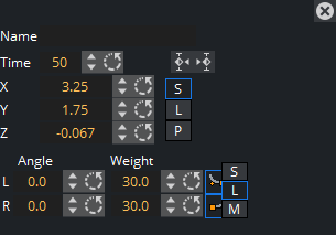
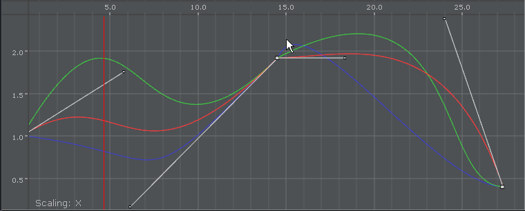
If you have animated the scale, you can scale along up to all three axes. To change all three scale values, in the object editor you find an input box for X, one for Y and one for Z. There you can change if the values should be Locked or if you change them proportional (Prop) or each Single value. In the spline editor, three different splines are shown (when Prop or Single is selected), one for every axis. The red one is for the X-axis, the green one for the Y-axis and the blue one for the Z-axis. As you can only edit the currently selected spline, you must use three spline buttons at the top of the Dopesheet Editor (or shortcuts CTRL + Z, CTRL + X and CTRL + C) to select the spline you want to edit. For ease of use in the lower left corner you find an indication of which axis is currently selected.
Scale Axes, X, Y and Z
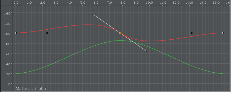
Material Key Frame Editor Properties
With a Material Key Frame, in addition to the default options, it is possible to define color.
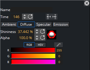
If a material has been animated, the object editor for the Key Frames shows a Material Editor. This allows you to conveniently the change the material. In the spline editor, two different splines are shown. The red one is for the alpha value (1), the green one for the shininess (2). As you can only edit the Key Frames/handles of one spline, you must use the number keys in the Stage Editor Bar to select the required spline. For ease of use in the lower left corner you find an indication of which parameter is currently selected.
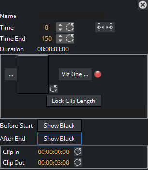
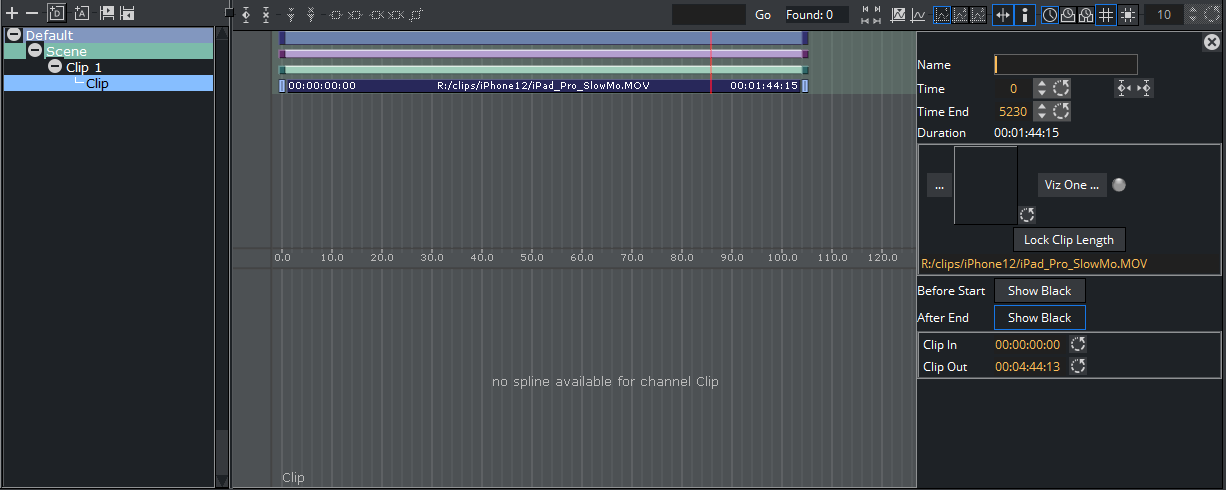
Clip Key Frame Editor Properties
-
Name: Sets a name for the Clip Key Frame.
-
Time/Time End: Sets the start and end time, in fields, of the Key Frame.
-
Duration: Sets the time duration of selected clip Key Frame as defined by Time/TimeEnd.
-
Clip: Selects a clip to use when the
 is clicked.
 -
Viz One: Selects a clip from Viz One (see Transfer Clips From Viz One).
-
Lock Clip Length: Locks automatic length adjustment. Keyframe maintains length for set clips. Useful when exporting the scene after making adjustments to the clip length in the stage, as this keeps the clip length as designed, and not revert to the length of the clip file.
-
Before Start: Sets what should happen before the clip starts to play within the animation. If the button is disabled, it shows the in-frame. If the button is enabled, it shows black until the animation gets to the clip.
-
After End: Sets what should happen after the animation leaves the clip Key Frame. If the button is disabled, it shows the out-frame. If the button is enabled, it shows black.
-
Clip In/Out: Sets the time the clip comes in and goes out.
Example:
Time = 50
Time End = 250
Clip Length = 4 sec (50i clip)
Clip In = 00:00:01:00
Clip Out = 00:00:03:00
The clip playback starts one second after the Director starts. The clip starts at frame 25 and ends at frame 75. Because the Key Frame duration is twice as long, the clip part is played twice.
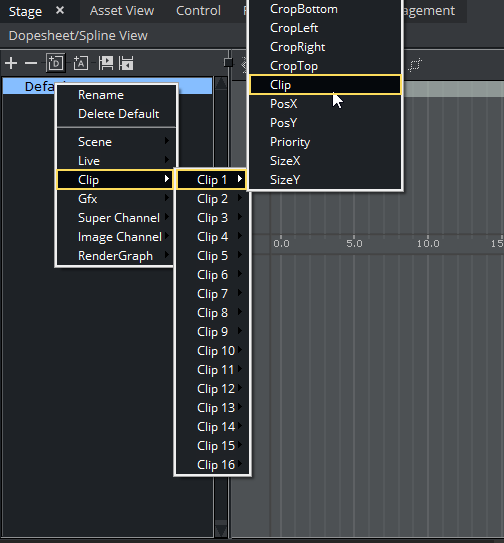
To Add a Clip to the Stage
-
Right-click the Director where clip is to be added.
-
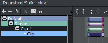
Select Clip <number> from the Clip menu, then choose Clip. To open the clip Key Frame editor, click the Clip Key Frame in the Dopesheet.
-
To define the clip, you can either browse for a local clip, drag a clip from the Graphic Hub or select a clip from Viz One.
Adding Camera Events Using Key Frames
The Stage Editor also allows the designer to change the active camera in a scene by using key-frames.
To Add a Basic Camera Switcher
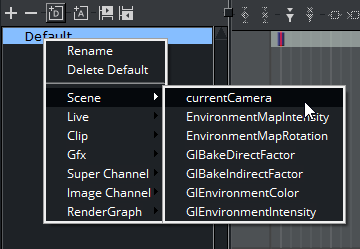
-
In the Stage Tree, right-click a Director and select currentCamera from the context menu. This adds a channel called Scene with currentCamera as an actor, with two key-frames.
-
Select the first key-frame. In the Actor Editor, enter a descriptive Name and a Value for the initial camera position. The default value is 1, which translates into Camera 1.
-
Select the second key-frame. Enter a descriptive Name and a Value for the second camera position in the Actor Editor.
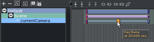
If you play this animation, Frame 0 up to 20.600 shows camera 1, then switches to camera 2 etc....