
Viz Artist
Version 3.10 | Published May 03, 2018 ©
Real Time Global Illumination
Global Illumination (GI), or indirect illumination, is a general name for a group of algorithms used in 3D computer graphics, that are meant to add more realistic lighting to 3D scenes. Such algorithms take into account not only the light that comes directly from a light source, direct illumination , but also subsequent cases in which light rays from the same source are reflected by other surfaces in the scene ( indirect illumination) , whether reflective or not.
If you do not have a license for the Real Time Global Illumination, contact your local Vizrt Support or send an e-mail to license@vizrt.com to obtain a time-limited demo license or a full license.
This section contains the following information:

Introduction to the Global Illumination function of Viz Artist 3.9
Introduced in Viz Artist 3.9, Real Time Global Illumination allows you to create Lightmaps and Ambient Occlusion maps that are modifiable in real time. This technique is based on the lightmap functionality widely used in leading game engines. When activating GI, you need to specify the computation settings, and precompute the Global Illumination and Ambient Occlusion maps. In Viz Artist, you find this feature section Scene Settings -> Global Illumination. The details of the settings are described below.
Working with Global Illumination
In general, Global Illumination requires 2 UV sets on any geometry that should be computed with GI: one UV set used for texture mapping, and one UV set used to create Lightmaps. There are two ways to create the Ligtmap UVs to get GI working properly. You can either import an .fbx-file with two UV sets that you have created by yourself. The first UV set must be used for texture mapping, and the second UV set is only used for Lightmaps. Or, you can use the first UV set (UV for texturing), and let the GI system calculate the according UVs for Ligthmaps.
Global Illumination has an advanced algorithm that can extract the UV coordinates of your first UV set, and automatically create UVs for the Lightmaps. The better the layout of your unwrapped UVs for texture mapping are, the better the GI system can generate the Lightmaps based on this information. The most efficient way is to create your own UVs for Lightmaps. Here, it is important to have your UV layout in the range from 0 to 1. Also, all UVs for Lightmaps must be unique and non-overlapping, otherwise GI cannot compute all Lightmaps. In general, the layout of the UVs for Lightmaps look different than the layout of UVs for texture mapping. There are several tutorials available online concerning how to create UVs for Lightmaps.
The following is an example of correct UV Layout for Lightmaps. In the image below, you see the UV layout of the second UV channel, which is used for lightmaps only.
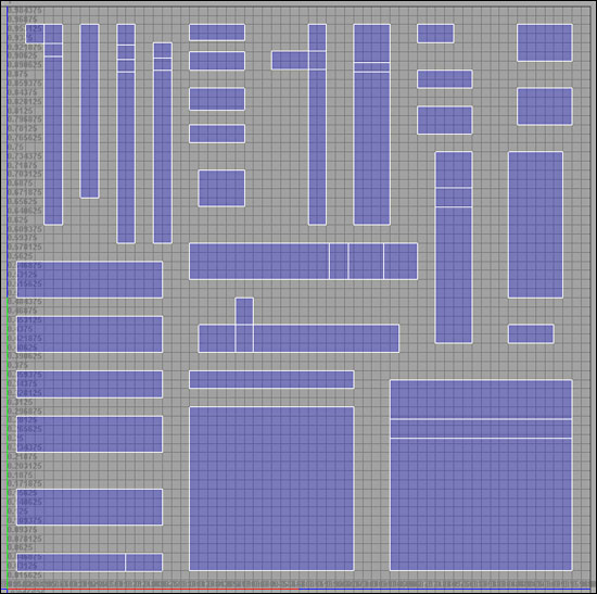
Precomputed Lightmaps do not use any memory on your GPU, so the texture memory of Viz is not reduced when having Lightmaps computed. The Lightmaps are not visible on your objects/geometries in the scene tree, as they are applied to the rendering pipeline in the render window.
Global Illumination settings
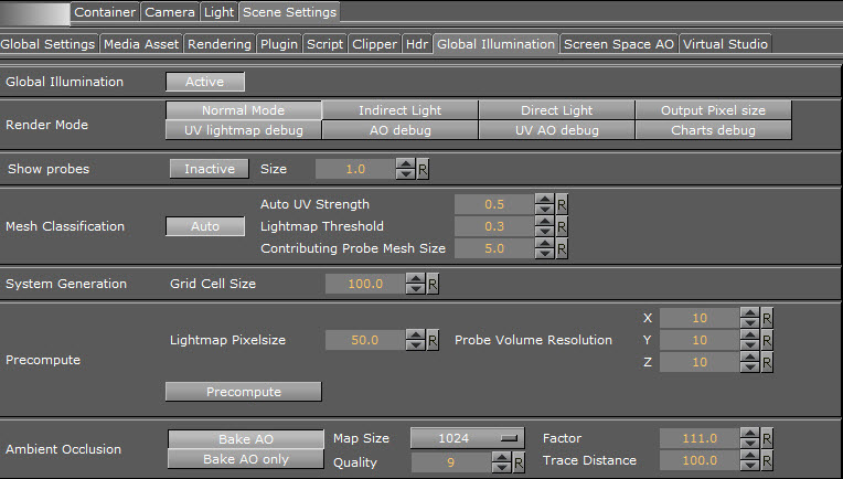
Global Illumination
Available settings: Active / Inactive.
This function enables or disables Global Illumination for your scene. For the final result, Lightmaps must be precomputed. If no Lightmaps are precomputed, it will enable a general pixel shading for your scene.
Lightmaps are stored inside the Viz Graphics Hub. When saving as a new scene (Save as), the Lightmaps is precomputed again as theyare stored and linked to the UUID of your scene. If you have already calculated the Lightmaps, switching between Active and Inactive loads or unloads them. The time required to load and unload lightmaps depends on the size of your scene and Lightmaps. While loading the scene, the lightmaps are copied from the Graphic Hub to a local folder, for faster loading times. When the scene is open, the lightmaps files can be found in the Windows temporary folder:
Example
Example: C:\Users\[user name]\AppData\Local\Temp\vizrt\Viz3\
The folder name the Lightmaps are stored in corresponds to the UUID of the scene they belong to.
Render Mode
Available settings: Normal Mode / Indirect light / Direct Light / Output Pixel size / UV lightmap debug / AO debug / UV AO debug / Charts debug
These are different visual modes for debugging the different render passes: the Ambient Occlusion render pass, the Indirect Light render pass, and the Direct Light render pass. You can also debug the Pixel Size, which controls the quality of the Lightmaps, or view the UVs for the Lightmaps, Ambient Occlusion, or the UV Charts. Normal Mode presents all maps together as a final result.
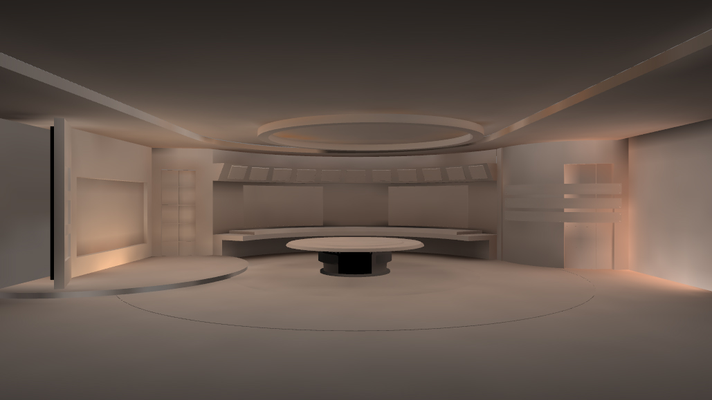
Render Mode Examples for Global Illumination
|
Render Mode |
Visual Example |
|
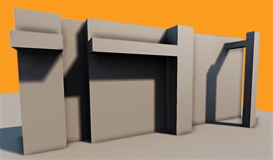
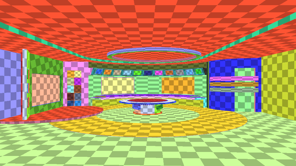
Global Illumination Normal mode This view represents the final output, with direct light, indirect light and ambient occlusion. |
|
|
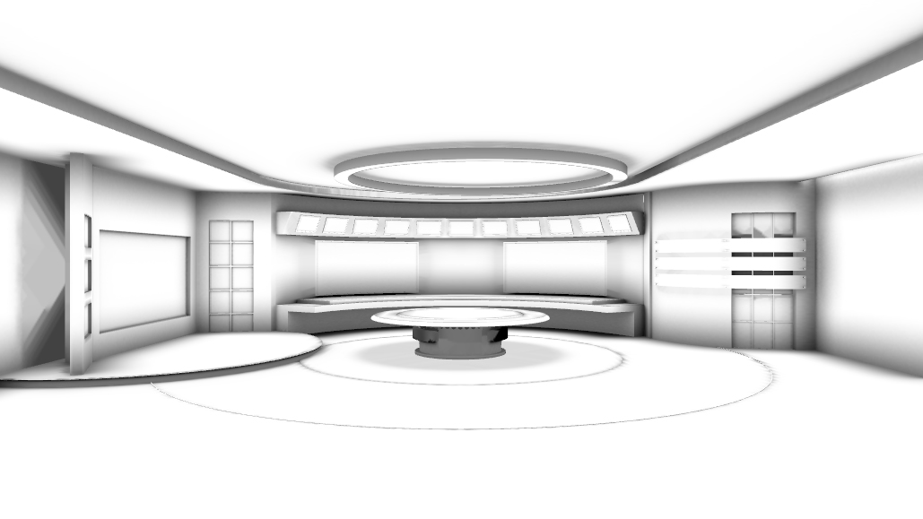
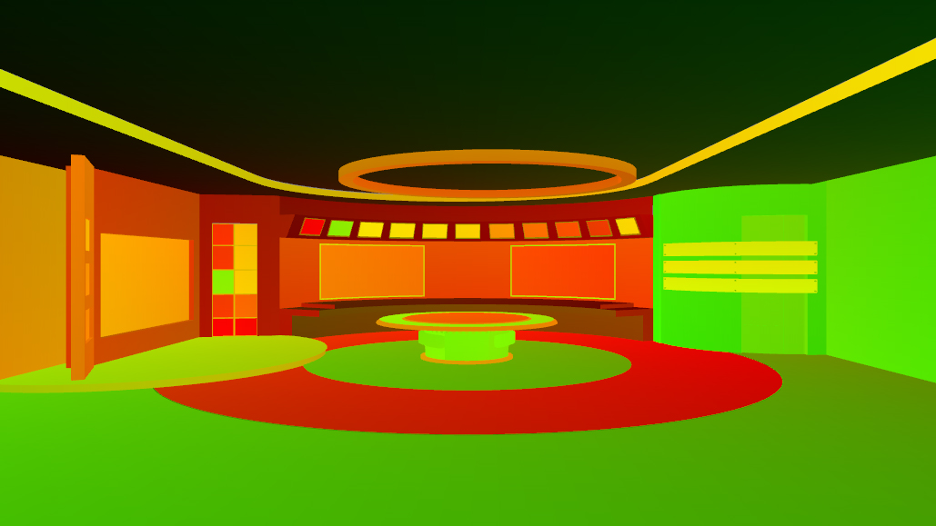
Global Illumination Indirect Light This view is represents the direct light (Global Illumination) only. |
|
|
Global Illumination Ambient Occlusion This view is represents baked Ambient Occlusion map only. |
|
|
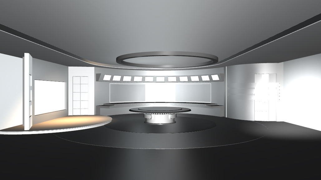
Global Illumination Direct Light This view is represents direct light only. |
|
Debug modes for Global Illumination
|
Debug Mode |
Visual Example |
|
Global Illumination Pixel Size This view shows the output of the Lightmaps in pixel size. |
|
|
Global Illumination UV Lightmap debug mode This view shows the lightmap UV's only. |
|
|
Global Illumination UV AO debug This view shows the ambient occlusion UV's only. |
|
|
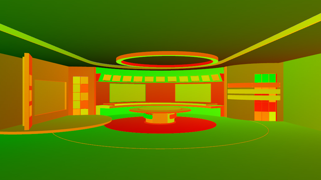
Global Illumination Charts debug This view shows the individual UV charts. |
|
Show Probes
Enable or disable debug view for the light probes inside your set. The light probes provides you with a visual representation of how light is distributed within your scene. The Size parameter adjusts the size of the light probes in the viewport, but does not influence computation of the Lightmaps or light probes themselves.
Be aware that not every object can be lit by lightmaps, due to the complexity of the UVs. This applies especially to organic shapes, for example, a statue. Objects that cannot be lit by lightmaps will be probe-lit.
Mesh Classification
This is the most important setting of Global Illumination. Mesh classification automatically classifies meshes for Lightmaps and light probes, and creates the necessary UVs for them. If Mesh Classification is turned Off, only the UVs from the second UV channel is used to generate the Lightmaps. If you set it to Auto, Mesh Classification generates the UVs for the lightmaps from your first UV set of your geometries/meshes. The computation of Global Illumination is faster when a second UV set is available, as analysis of the geometries and generation of additional UVs is not required.
Mesh Classification can be adjusted with the following parameters:
-
Auto UV Strength: This controls how aggressively the Auto UV process flattens the meshes onto planes. Lower values lead to better UVs with less overlap. Thus, more meshes are classified as lightmap-lit, at the expense of larger UV space requirement. Higher values result in worse UVs, with more meshes classified as probe lit, and lower UV space usage.
-
Lightmap Threshold: This controls the threshold where Auto UVs are considered bad enough that a mesh should be probe-lit instead of lightmap-lit. Lower values increase the number of meshes probe-lit, and higher values increase the number of meshes that are lightmap-lit.
-
Contributing Probe Mesh Size: This controls how big a probe-lit mesh and it's surroundings have to be, before it comes a Contributing Probe.
System Generation
Grid Cell Size: The scene is split up into systems of cubical cells of this dimension in World units.
Precompute
Lightmap Pixel Size: This defines the Output pixel size for lightmaps. If the pixel size is set too low, depending on your scene complexity, you will not be able to generate all Lightmaps. This is because there is only a certain amount of memory available for all Lightmaps.
Using a smaller pixel size value will increase quality, and will cause an error message when the maximum amount of pixels is exceeded. When adjusting the pixel size, make sure you are working with real world coordinates and transformations/scaling on your meshes/scene.
For a good start with low computation time, set the pixel size to 50 on a 1 x 1 meter cube (two pixels in one cube).
The following two examples shows the difference when using a lightmap pixel size of 50, and a pixel size of 10. Lower pixel sizes increase quality, but also increases computation time.
Example
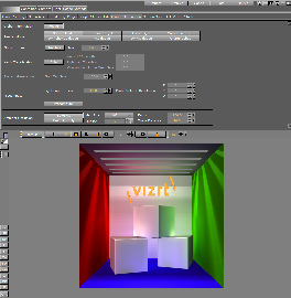
Example 1:
In this example there is visible noise in Normal Mode, and also in the Indirect Light render pass. The pixel size used in this scene is 50.
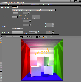
![]()
Example
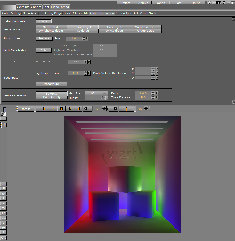
Example 2:
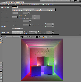
In this example there is no visible noise. The pixel size used in this scene is 10.
![]()
Probe Volume Resolution: This defines the number of probe samples in the scene in x-, y- and z axis. When activating the Show Probes feature you can see the amount of probes in your scene. When chanhing the amount of probes you need to recompute the Lightmaps again to see the changes.
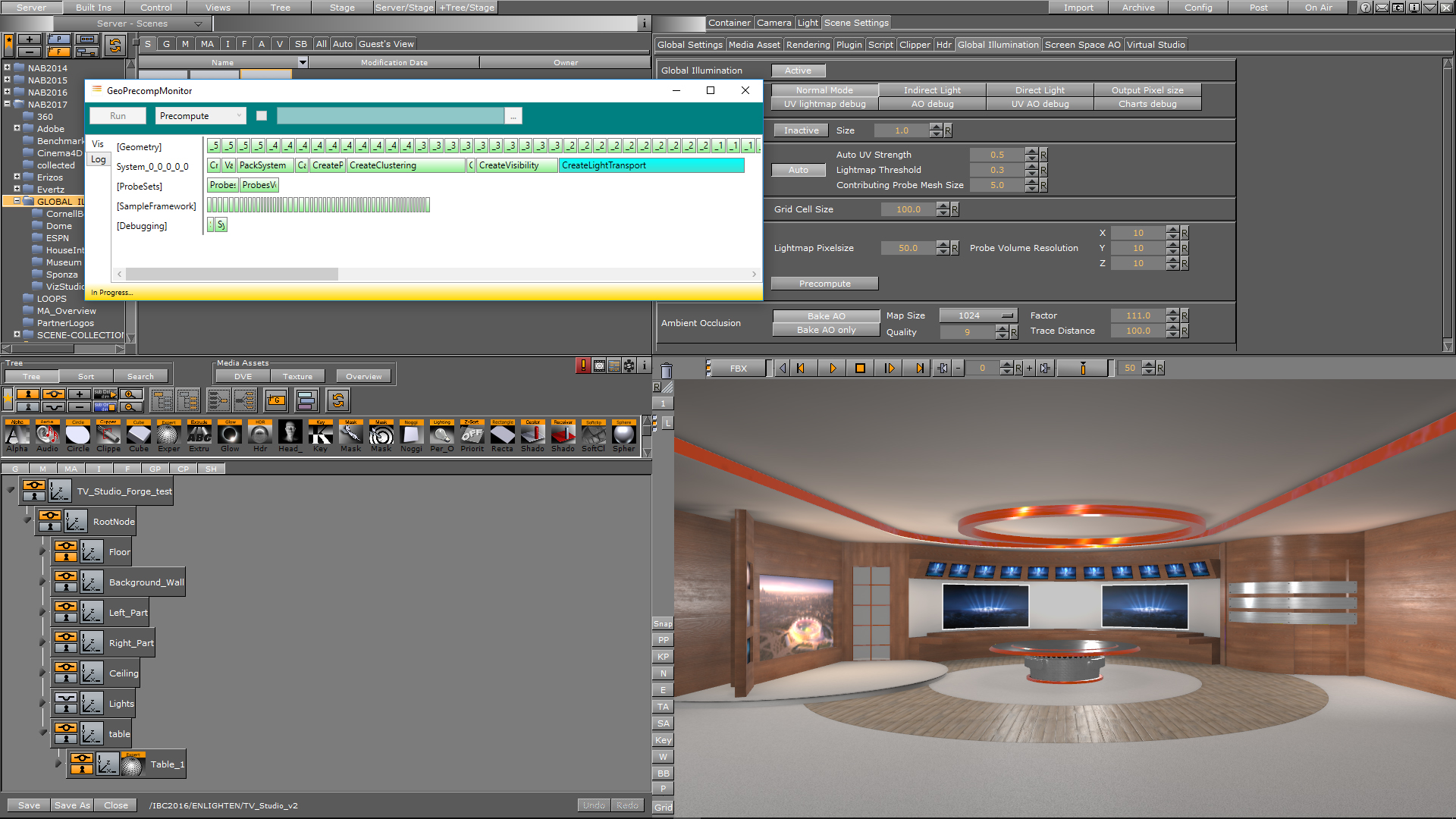
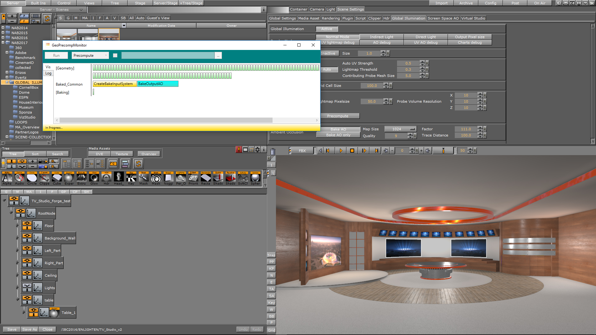
Precompute: Pressing the Precompute button to generate all lightmaps. An overlay window appears, showing you detailed debug info. The first overlay window displays the scene analysis procedure. When this task is done, a second overlay window appears, displaying the baking procedures.
Note: You must precompute all maps again each time you add additional objects to your scene.
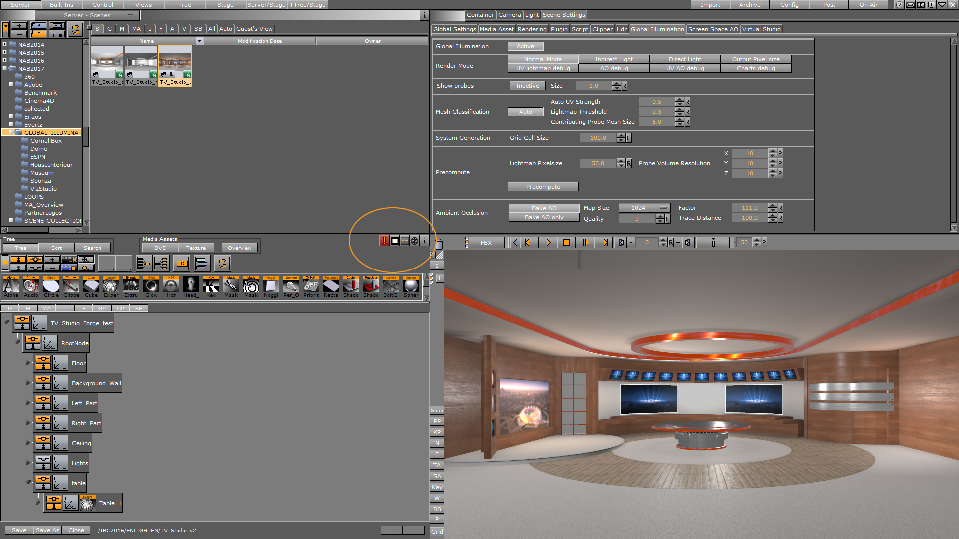
As individual objects cannot be computed on their own, precompute always recalculates the whole scene. If you have wrong UVs, or any other issues, for example with the pixel size, a window with error messages will appear. You can read the detailed error messages and computation information in the log-file. The error messages are available in the scene info menu, which turns red in the case of any computation issues.
Precompute Computation Examples
|
|
|
|
1: The Geo Precompute Monitor during scene analysis and UV preparation. |
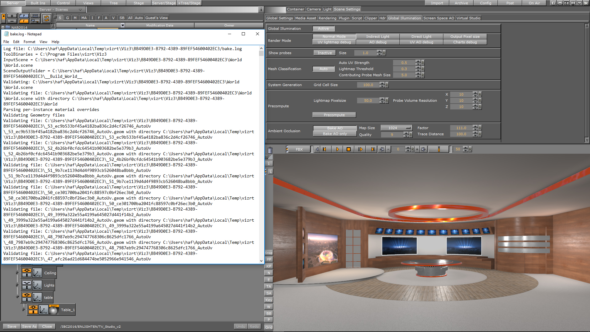
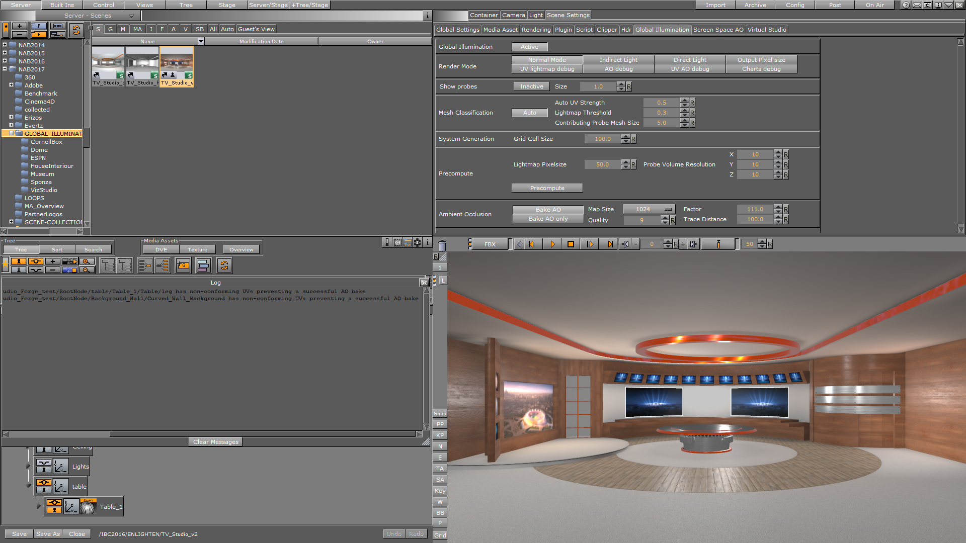
4: The log-file with computation information and error messages. |
|
2: The Geo Precompute Monitor during the lightmap baking process. |
5. The scene info error log. A red icon indicates that errors occurred during computation. |
|
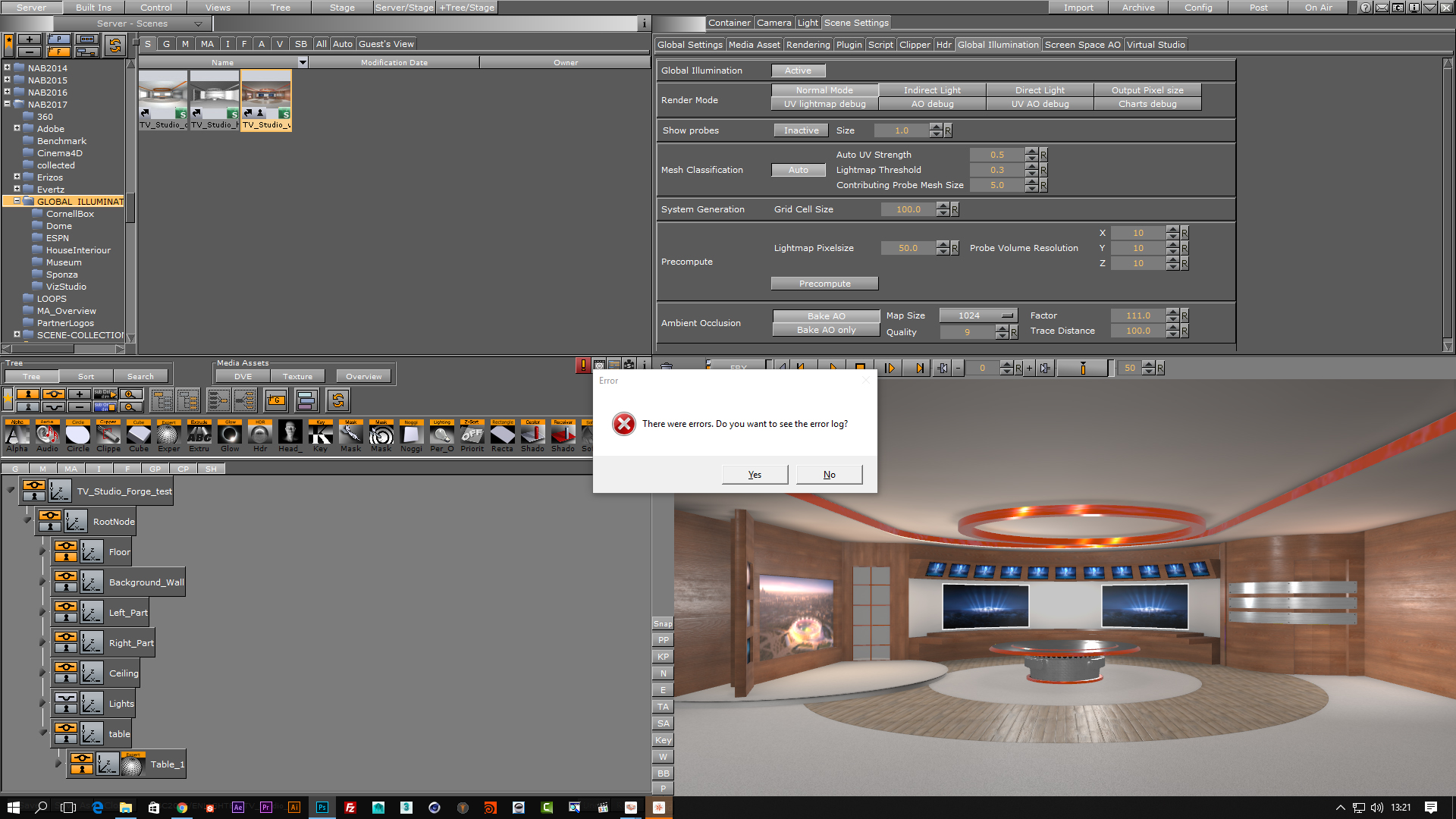
3: A pop-up window when errors occurred during computation. |
6. Error messages in the scene info error log. This example shows some geometries with non-conforming UVs preventing a successful AO bake. |
Ambient Occlusion (AO)
Bake AO: When active, every bake process (precomputation) also recalculates the AO maps. When Bake AO is off, only the indirect light maps are calculated when you press the Precompute button. Enable Bake AO only to recalculate the AO maps only. This is useful when you only to play with the AO without adjusting your Global Illumination parameters, as it reduces the computation time by only calculating the AO maps. For best results, always run a full computation process, as the GI and AO maps will not work properly together if computed with differences. This can happen if you change or delete objects in the scene.
Map Size: Specify the size of your AO maps for the scene, ranging from 512 pixels up to 16K. The default setting is 512 pixels.
Quality: Here, you can increase or decrease the quality of your AO maps. Increasing quality will also increase calculation time. The quality setting has a range from 4 to 17. The default setting is 8.
Factor: Change the factor to influence the strength/blending of the ambient occlusion. You can change the factor at any time without recomputing the meshes/scene.
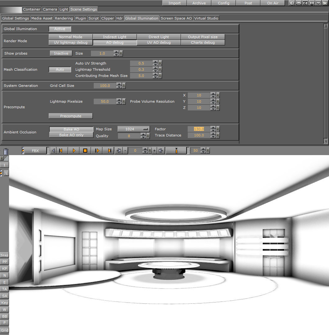
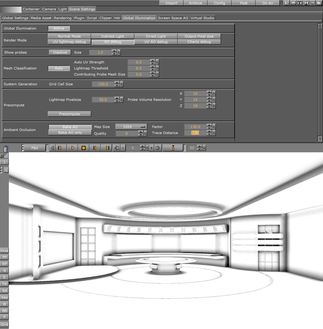
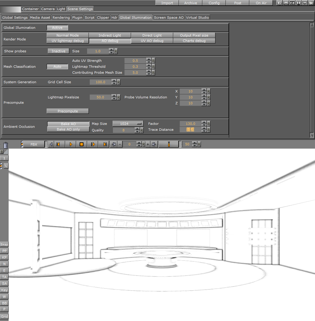
Trace Distance: This parameter sets the distance where a point shall be considered occluded. When you change this value, you cannot see the results in real time, as you must recompute the AO maps for the changes to take effect. Usually, the double value of the Lightmaps pixel size is used here; if your lightmap pixel size is set to 50, you should have a value of 100 in the Ambient Occlusion Trace Distance field. Since this comes down to the individual designer's style, use any value you like here. The following images show some examples:
|
Trace Distance: 100 |
Trace distance: 50 |
Trace Distance: 10 |
|
|
|
|
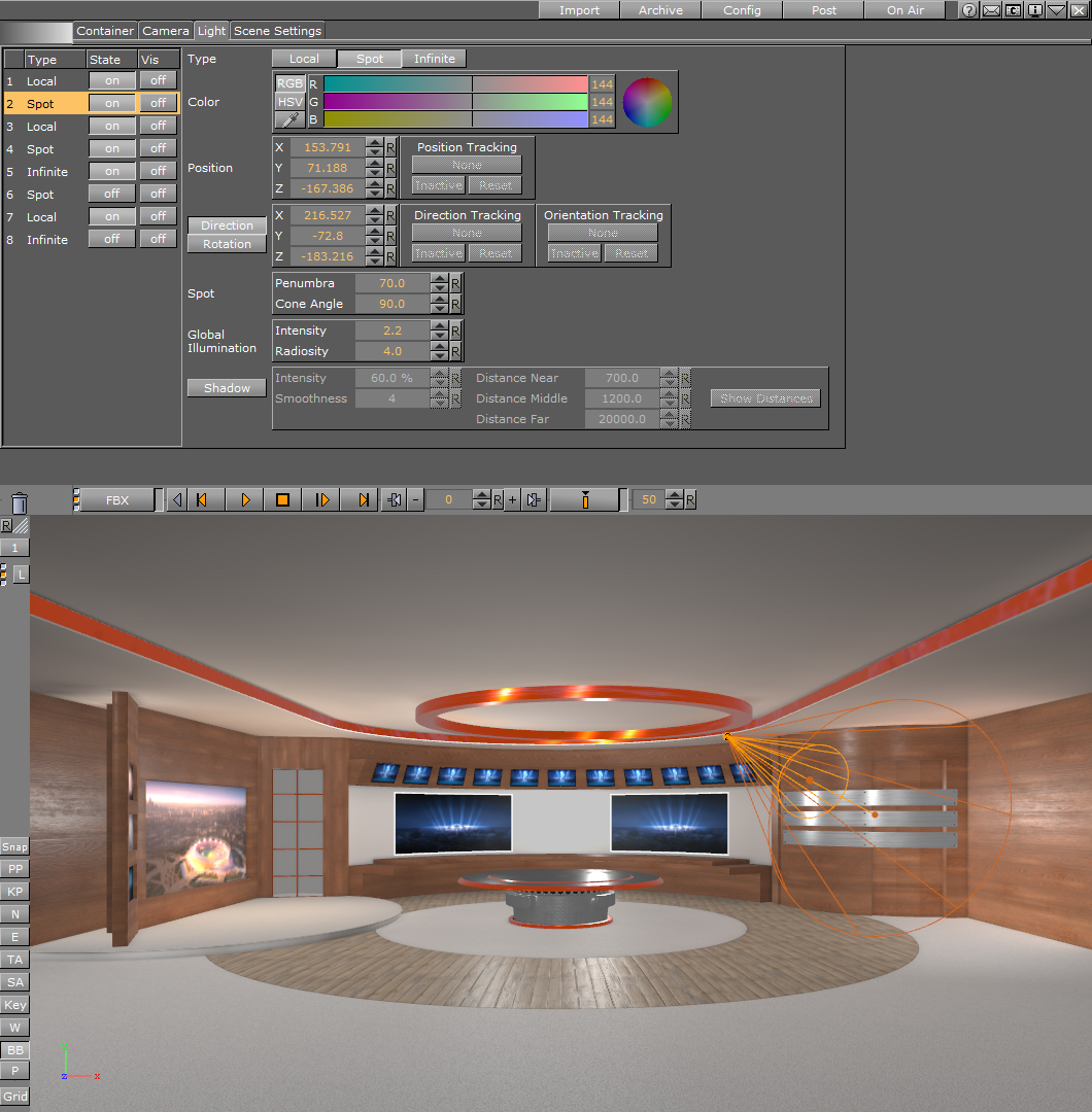
Finally, you can now play with the Radiosity setting in the Light Editor:
The input controls for Global Illumination are only visible in scenes where Global Illumination is set to Active.
Creating a Scene with Global Illumination
First, you need to import a geometry or scene with proper UVs and normals. This can be either just one UV set with unwrapped UV coordinates to be able to do a proper texture mapping and extract the lightmaps from this UV set. You can also import an .fbx-file containing the second UV set, with a layout for lightmaps created in your preferred 3D application. On your imported geometries make sure the normal orientation is facing outwards, flipping the normals with the Expert plugin will lead to wrong computation results. Do not forget to turn Auto Mesh Classification on or off, depending on your existing UV sets.
Next, if your scene is not already modeled or imported with the proper size, you need to set up the real world size of your scene before you do the baking. Then place some lights in your scene. After this, adjust all the parameters described above and run a test bake, to see if you get any error messages concerning UVs or baking. If your render passes look good from the debug views, no error messages appeared, or at least no visual errors are visible, you can start working on the detailed light setup.
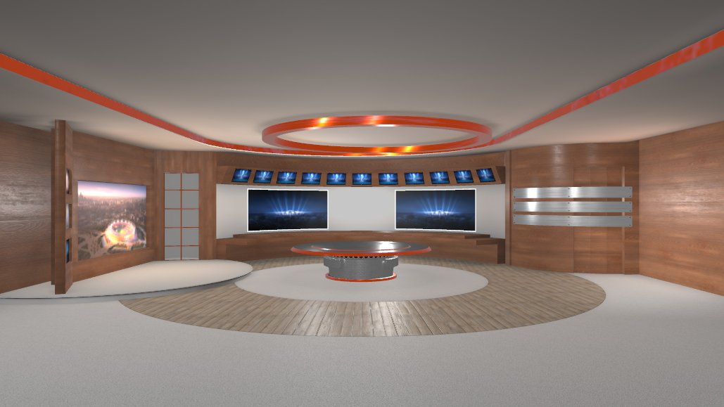
All the light setups, color, type, transformation, can be done at any time now, without a need to recompute the whole scene. This is the benefit of working with lightmaps. It is very important to increase the radiosity setting of the lights that light up the whole scenery, using the Light Editor. Be aware that Lightmaps are static maps that react in real time to the GI parameters. They are not dynamically calculated with animations. When you have an object, like the Cornell box example above, and animate the rotation of one of the cubes inside the Cornell box, you will see wrong colors reflected during the rotation. This is because the lightmaps are statically projected onto geometries. When rotating the middle cube of the Cornell Box example, which is receiving a green color from the green wall next to it, it will not turn red when rotating to the other side, because lightmaps are static. The same applies to Ambient Occlusion maps. Whenever you want to animate an object, you should not compute the lightmaps or Ambient Occlusion maps for it, as otherwise the result will not look correct. If an object is hiden in the Scene Tree it will not be calculated with GI.
After setting up all the parameters and running a successful precomputation process, switch to the Indirect Light debug view from the Global Illumination pane, to see how the radiosity intensity of the light affect your scene. Experiment with different lights and radiosity settings to get your desired result. During this process, you should switch between the debug view for Indirect Light and Normal Mode, to see how much GI affects in your scene. Now, you can start refining your scene with adding Substance Shaders to your scene to increase realism. Compared to using regular plain textures, substance's light reflection is aiming a physical correct behaviour depending on the shader properties. This is something a regular texture will not do.
If you want to work with plain textures only, this is possible. Be aware that no other material and effect shaders than Substance Shaders are supported in combination with Global Illumination.
To get your light color correctly spread into your scene, you need to apply a material to every geometry and use the eye dropper tool of the material editor to get the correct color from the texture or shader used on the selected geometry. Otherwise, radiosity cannot blend the surface color into the set, since it is not possible to extract the color directly from textures or shaders. Applying a material with color will not influence your Substance Shader, as this material color will only be used for the color bleeding of the radiosity.
Limitations
Global Illumination is built to work in conjunction with Physically Based Rendering (PBR) materials, to get the most realistic results. In general, it is common to use Global Illumination in conjunction with Substance shaders. Substance shaders are the only available PBR shaders for Viz Artist. Therefore, any other material shader, such as RTT and others, will not work with Global Illumination. When using a feature which is not supported by Global Illumination, you will get an error message in the scene info. Error messages in the scene info are indicated by a red info icon.
The following list are examples of features and/or plug-ins that are not supported in combination with Global Illumination:
RTT Shaders, Softmask-, Framemask-, ImageMask-, Fluid Effect-, Water Shader Plugin, Drop Shadow-, Emboss Plugin, Anisotropic Light Plugin, Cartoon Shader, Gooch Shader, Lighting Shader, Normal Map Plugin
Filter Blend-, Filter Blur-, Filter Color Balnce-, Filter Radial Blur-, Filter Sepia-, Filter Sharpening Plugin, HDT Plugin, etc....