Viz Artist
Version 3.10 | Published May 03, 2018 ©
Spline Strip
![]()
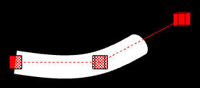
The Spline Strip plug-in is used for creating 3D interactive loft extrusions which are able to be animated in their length and surface. You can use modifiable lines, circles or rectangles for the extrusion. Arrows and terrain alignment are also supported.
Note: This plug-in is located in: Built Ins -> Geom plug-ins -> Default
This section contains the following topics:
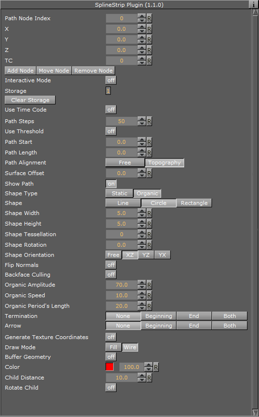
Spline Strip Properties
-
Path Node Index: Defines where Path Nodes get added, moved or removed. The first node within a path owns the index 0. If you add nodes at the end, then the Path Node Index is increased automatically to provide a simple path generation.
-
X, Y and Z: Sets the Path Node’s X, Y and Z-position.
-
TC: Sets the Path Node’s TC-position.
-
Add Node: Adds a path node at the current Path Node Index with position X, Y, Z and TC.
-
Move Node: Moves the current path node to your required X, Y, Z and TC position.
-
Remove Node: Removes a path node at the current Path Node Index.
-
Interactive Mode: If you have finished the process of setting path nodes then you are able to edit it simpler by mouse. Just drag and drop the shown nodes to a new position. Left Mouse Button: move node in XY. Middle Mouse Button: move node in XZ.
-
Interactive Orientation: World, Local, View. Move nodes interactive with world-, local-, or viewpoint- coordinates.
-
Node Size: Sets the interactive node’s size.
-
Storage: Is used for storing your defined path nodes in a #-separated string. It is possible to edit nodes directly in the Storage Text field.
-
Clear Storage: Clears the spline strip object and its storage.
-
Use Time Code: Activates Time Code functionality.
-
TC Current: Contains the current Time Code of an external Time Code source.
-
TC Start: Sets the starting point of your Time Code animation.
-
TC Reference: If you are using more than one spline strip then they probably won’t start all at the same Time Code position. But you can change that by a simple time shift with the Help of TC Reference.
-
Path Steps: Defines SplineStrip tessellation.
-
Use Threshold: You can optimize your spline strip with that option. Path Steps are added at necessary positions only. So the number of Path Steps increases with a decreasing Threshold.
-
Threshold: Sets the Threshold for Path Steps generation.
-
Path Start: Sets the starting point of the path geometry.
-
Path Length: It defines the length of our spline strip object. Feel free to animate that value!
-
Path Alignment: Fits the spline strip to Terrain plug-ins in Viz Artist/Engine. (e.g. use Terrain for drawing paths over a mountain). Available options are; Free and Topography.
-
Surface Offset: Shifts Path on Y axis.
-
Use Surface Normal: If activated then the surface offset is computed via terrain normals.
-
Show Path: Shows the Path which you have defined at the beginning. This option is quite helpful when you are editing Path Nodes.
-
Shape Type: If you activate the Organic Mode, your spline strip will start to wobble in dependency of the adjusted Organic Amplitude, Organic Speed, and Organic Period’s Length. Available options are; Static and Organic.
-
Shape: Defines the shape used for the loft extrusion. Available options are; Line, Circle and Rectangle.
-
Shape Width: Sets the shape’s width.
-
Shape Height: Sets the shape’s height.
-
Shape Tesselation: Defines how many steps are used to draw the required shape.
-
Shape Rotation: You are able to move the spline strip shape up to 360 degrees.
-
Shape Orientation: When set to Free, shapes are rotated in dependency of the adjusted Shape Rotation value. When set to XZ, YZ or YX, shapes are auto rotated to obtain a constant SplineStrip width in the required aspect. When set to Terrain, shapes are rotated to fit the terrain beneath them.
-
Translate Vertices To Terrain: Moves every single vertex to fit the terrain. This mode only makes sense if you are using Line extrusion.
-
Flip Normals: Flips spline strip normals.
-
Backface Culling: Switch off drawing spline strip’s backside.
-
Organic Amplitude: Adjusts the animated diameter reduction from 0% to 100%.
-
Organic Speed: Changes speed of organic mode animation. Also negative values are allowed.
-
Organic Period’s Length: Sets the diameter reduction function’s period length.
-
Termination: Closes our spline strip object at the Beginning, End or at Both sides. Available options are; None, Beginning, End and Both.
-
Arrow: Puts an Arrow to the Beginning, End or Both sides. Available options are; None, Beginning, End, Both
-
Object Width: Changes arrow width.
-
Object Height: Changes arrow height.
-
Object Length: Changes arrow length.
-
Object Tesselation: Changes arrow tessellation.
-
Generate Texture Coordinates: Activate this function if you are using vertex maps on your spline strip.
-
Stretch Texture to Path Length: If activated then the map is stretched to the actual path length.
-
Draw Mode: Switch between fill- and wire-frame mode. Available options are; Fill and Wire.
-
Buffer Geometry: The whole spline strip data is buffered to memory. If you use spline strips with a huge number of vertices then Buffer Geometry is able to improve performance. Activate this mode only if you do not use any kind of animation in your current spline strip.
-
Color: Defines path’s and interactive-mode-node’s color. Color is also used if Wire is activated and no maps are applied onto your spline strip object.
-
Child Distance: Defines distance between path end and child container.
-
Rotate Child: Activates child container rotation.
To Create a Simple Spline Strip
-
Create a new Container.
-
Add the Spline Strip plug-in.
-
Open the Spline Strip editor.
-
Use all default values.
-
Click Add Node.
-
Change X to 100.0.
-
Click Add Node.
-
Change X to 200.0, Y to 50.0.
-
Click Add Node.
-
Set Shape Width and Shape Height to 50.0.
-
Set Shape to Circle.
-
Set Shape Tesselation to 20.
-
Set Path Lenght to 150.

-
Optionally, click Interactive Mode.
-
Change Node Size to for example 15.0.
-
Activate script and plug-in events in the Scene Editor by clicking the E button.
-
Drag and drop the small Cubes as required.