
Viz Artist
Version 3.10 | Published May 03, 2018 ©
State Transition Animation
As previously mentioned, the make-up of a toggle-layer in a Transition Logic scene is a relationship between the Toggle plug-in and a Director in the stage. Through the use of the Director's timelines, it is possible to animate between different variations in the design, called states. In order to make use of these states, each object scene refers to a specific toggle-layer and desired state.
Toggle layer states

Animating between different toggle layer states is called state transition animation. The example above shows a lower third’s backplate being animated from a narrow version to a wide version (two states).
Defining States
A toggle layer is required to have a default state named O. The O state is often referred to as the Out state as it is the state the toggle layer will be taken to when the operator issues a Take Out command. This means that in most cases, this is also the state where the toggle layer’s referring foreground scene is no longer visible on-screen.
In addition to the O state, at least one additional state is required to run animations when taking items to air. Any state that is not the O state is often referred to as an in state, or visible state, because it most often refers to the state when a referring object scene is shown on-screen.
Tip: The master scene should be saved with the play head at the beginning of the timeline, which is equal to the O state. This will make sure that the scene is properly initialized in the O state.
Use the following conventions when naming states:
-
O states must be named in upper case only. This is a reserved state that is tied to the take-out command.
-
It is recommended to name states according to the referring control scene’s appearance or other distinguishing characteristic. For example, for a toggle-layer responsible for content displayed in the lower third of the screen that varies in size from large to small will typically have two states named LARGE and SMALL. A graphic placed over the shoulder of a presenter, where the graphics should switch between the left and right side of the screen, would simply be named LEFT and RIGHT, or OTS_LEFT and OTS_RIGHT, with OTS being short for Over The Shoulder.
-
To maintain consistency between designers, it is recommended to write all state names using upper case characters only. This will also make it simpler to implement the state change in later steps.

When taking an item which requires the SMALL state, the master scene will animate from the O state to the SMALL state, once that item is taken on air. When a take-out command is issued, the master scene will then animate in reverse to the O state.

Transitioning from a SMALL to an O state is achieved by using the animation from the O to the SMALL state. In such a case the animation will be played in reverse. If this is not required, you simply add another O state after the SMALL state, and create a new animation.

If the layer should transition from the small sized version to the large version, you simply add the state to the toggle-layer director, and create a transition animation for the layer going from SMALL to LARGE. This also requires that the LARGE state has an O state such that the graphics can transition and animate out from the LARGE state.
Identifying States
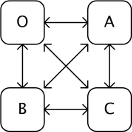
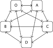
There are no hard limits to the number of states. However, increasing the number of states also increases the number of animations, and consequently the complexity of the scene. To decide the minimum number of animations required it is possible to do a Euler Walk (1).
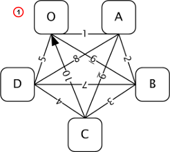
The Euler Walk, although not always possible, is defined as the optimal route taken to visit each point exactly once. However, the theory can be applied to Transition Logic to identify the minimum required states needed to connect each state to the others exactly once.
Straightening the Euler walk out onto the layer’s director will show the required transition animations:
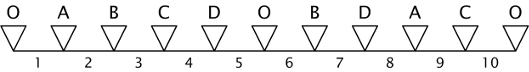
Note: When performing transition animations from one state to the other Viz Artist/Engine will search from left to right on the layer’s director for the correct combination of states. If the operator wishes to go from state A to B, Viz Artist/Engine will traverse the layer’s director for state A and look to the right and see if it finds state B. If a match is found, Viz Artist/Engine will perform the transition animation.
Looking at the above example director, it becomes clear that not all combinations can be found by traversing from left to right. If a change from state A to D is not found, Viz Engine will first traverse from left to right, then start to backtrack and traverse from right to left looking for a D from A animation.
When the minimum required animations have been discovered, it is time to add extra animations required by the overall design. For example, it might be desirable to add a transition from state B to O, to animate the layer out from state B in a different way than reversing the in animation. As an example, think of a lower third graphics animating in from the left, stopping, then animating out to the bottom. Adding new out states quickly increases the complexity of a layer. As all states are required to be connected to each other, it would not be advisable to simply make an O state in place of the B to C animation.
Detailed below are the minimum required number of transition animations for a graphics layer with a given number of states:
-
1 State:
-
Animations: Not possible.

-
-
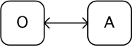
2 States:
-
Animations: Requires a minimum of 1 animation
-
-
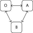
3 States:
-
Animations: Requires a minimum of 3 animations
-
-
4 States:
-
Animations: Requires a minimum of 6 animations
-
-
5 States:
-
Animations: Requires a minimum of 10 animations
-
-
6 States:
-
Animations: Requires a minimum of 15 animations

-